Introduction
In autonomous driving, there are several coordinate systems involved from the car’s sensors to global positioning, which are briefly organized below.
Sensor Coordinate System
Each sensor has its own coordinate system, which can be divided into relative measurement (measuring environmental information) and absolute measurement (measuring its own information) according to its measurement principle. Relative sensors such as cameras and LiDAR measure environmental information for indirect positioning, while absolute sensors such as IMUs, tachometers, and GPS measure their own motion (speed, position, attitude, etc.) directly for positioning. For relative measurement sensors, the measurement value is usually under its own sensor; while absolute measurement is usually measured by its own coordinate system relative to other coordinate systems (local or world coordinate system, etc.). The following is a summary of common measurement sensors.
Camera coordinate system
The camera as an environmental sensor can reflect the environmental information on the picture according to the projection principle. Each point on the picture can be projected onto the normalized plane of the camera by back-projection, and the camera coordinate system is shown in the following figure.
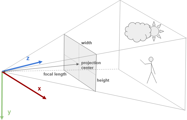
The orientation of the camera coordinate system is generally: X -> Right, Y -> Down, Z -> Front
Lidar coordinate system
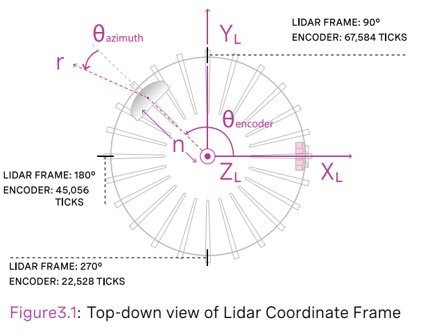
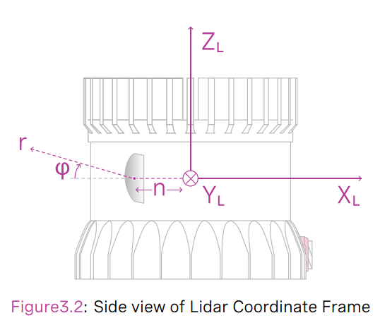
LiDAR can be divided into 2D and 3D, and each frame of information is a point cloud. Each point in the point cloud can be expressed in polar (distance and angle) or Cartesian (x, y, z) coordinates, which are in the LIDAR coordinate system. The orientation of the LIDAR coordinate system varies from model to model, in general the Z-axis and the LIDAR rotation axis coincide pointing upwards when placed flat, and the XY-plane is parallel to the ground, as illustrated in the following diagram of the Ouster OS-1-64 coordinate system.
IMU Coordinate System
Unlike cameras and LiDAR, IMU, GPS and tachometer do not collect environmental information, but directly measure the state of the sensor itself by different principles.
The measurement principle of IMU can be found in my previous blog: IMU Measurement Model. IMU can be divided into 6-axis and 9-axis, 6-axis IMU contains accelerometer and gyroscope. IMU itself has a coordinate system defined as shown below.
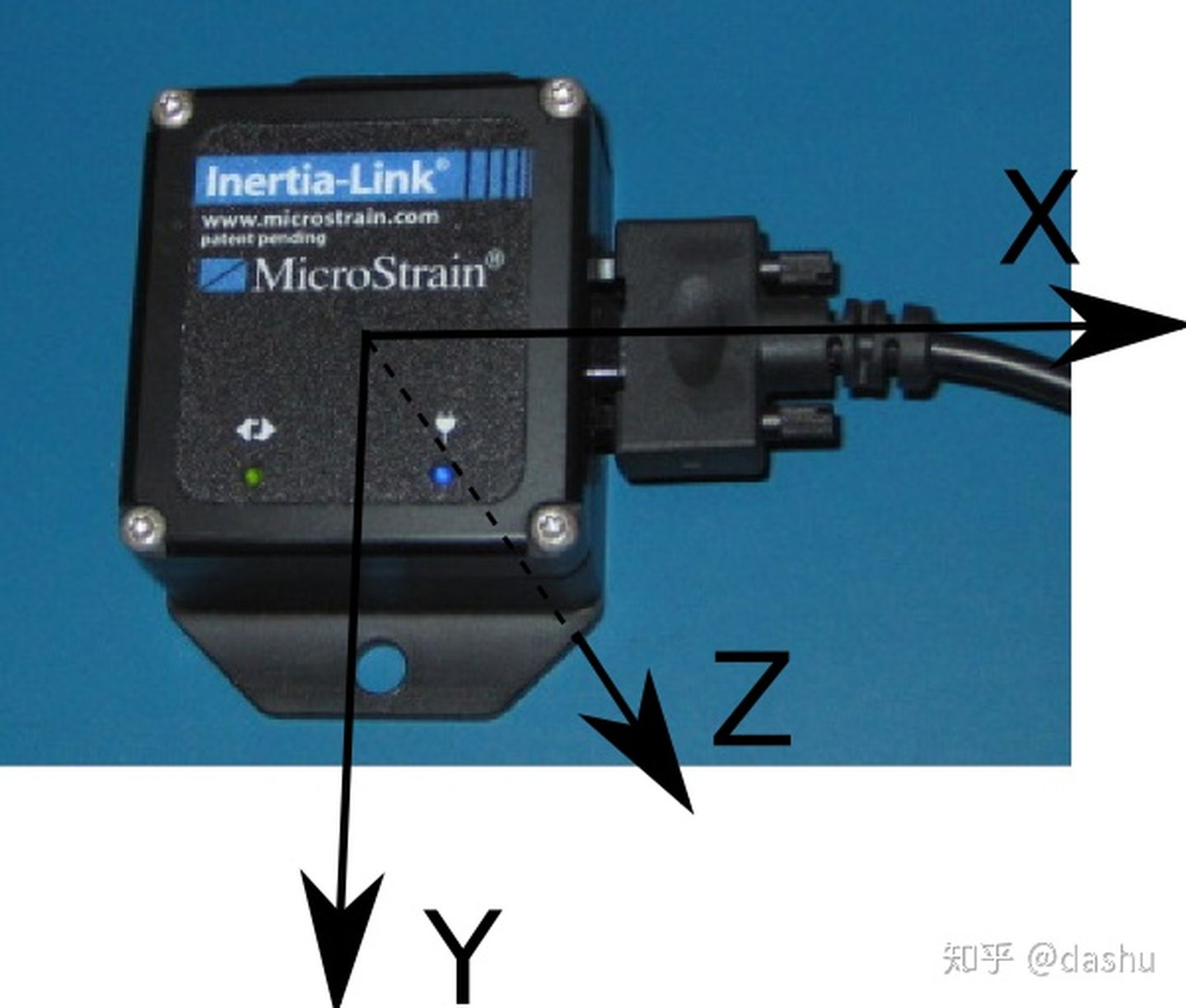
The measurements of IMU accelerometer and gyroscope are the acceleration and angular velocity of IMU coordinate system relative to the inertial system, respectively. The choice of inertial system can be different depending on the use scenario and accuracy requirements. For small range and short time positioning, we can approximate the local coordinate system as the inertial system, which is simpler to solve the carrier state, and for large range and long time with high accuracy requirements, we can choose the world coordinate system (ECEF coordinate system mentioned below) as the inertial system, which needs to consider the information of earth rotation The calculation is relatively complicated because it needs to consider information such as the rotation speed of the Earth and the altitude of the carrier.
GPS
GPS has no coordinate system, it measures the coordinates of the carrier in the world coordinate system (WGS84). It consists of longitude and latitude.
Tachymeter
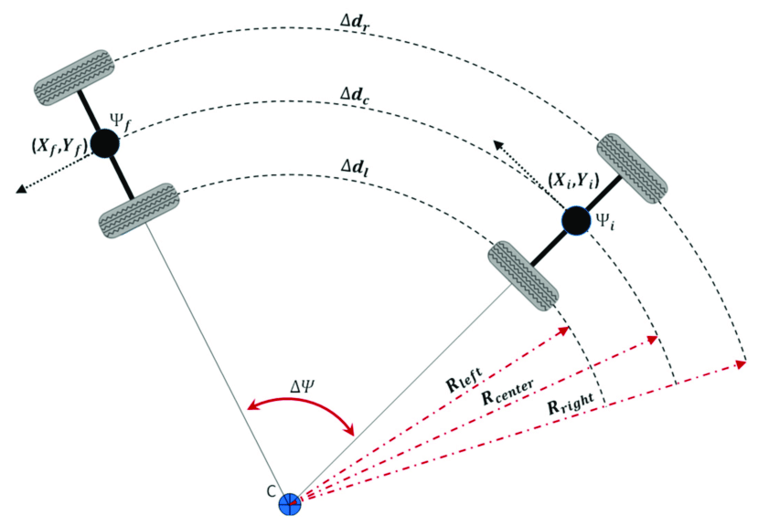
A wheel tachometer usually has no coordinate system of its own. The measurement of a single encoder is the speed of that wheel. The tangential velocity at the center of the line connecting the two wheels can be obtained by combining the encoders on both wheels with a checkpoint model. This is shown in the following figure.
Car Coordinate System
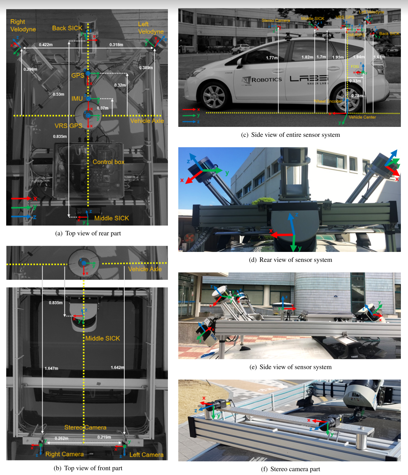
The automotive coordinate system is a human-defined coordinate system fixed at a point of the car. As a reference coordinate system of the car system itself and each sensor coordinate system are linked by external reference. The orientation of the vehicle coordinate system is generally FLU (Front-Left-Upper), and its position varies with different scenarios. point, as shown below. In some cases where there are few sensors, the IMU, GPS or some sensor coordinate system can also be used as the car coordinate system.
Navigation Coordinate System
The odometer in autonomous driving tracks the motion of the car in successive moments, leading to the concept of a navigation coordinate system. The navigation coordinate system is generally fixed at the position of the car at the starting moment. In the case where gravity can be aligned (with inertial sensors such as IMU), there are generally two directions, ENU (East-North-East-Earth) or NED (North-East-Earth), and if gravity cannot be aligned, the direction is the initial attitude of the car’s coordinate system. The car’s attitude measured by the odometer is the attitude in the navigation coordinate system. It can be considered as a local coordinate system compared to the world coordinate system.
World coordinate system
In practice, an unmanned vehicle may pass through the same area several times for positioning and map building. The origin of the navigation coordinate system is not the same every time, which obviously does not meet the demand. Therefore there is a need for global measurements to obtain the absolute position of the car on the Earth, which leads to the concept of a world coordinate system. The world coordinate system usually encompasses the whole earth and has its origin fixed somewhere on the earth (geocentric), in the form of geocentric and Dicard coordinate systems. Since the Earth itself is an (ellipsoidal) sphere, the conversion from the geocentric to the Dicard coordinate system needs to follow some kind of projection, which involves distortion and deformation.
Geographic Coordinate System (GCS)
Geocentric Geofixed Coordinate System (ECEF)
The geocentric ground-fixed coordinate system (Earth-Centered,Earth-Fixed, ECEF) has the origin at the center of mass of the Earth, the x-axis points to the intersection of the prime meridian and the equator, the y-axis is perpendicular to the xOz plane (i.e., the intersection of 90 degrees East and the equator), and the z-axis points to the North Pole, and its relationship with the navigation coordinate system (in the case of ENU) is shown in the following figure.
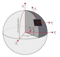
Geodetic Coordinate System (LLA)
Since the Earth’s surface itself is ellipsoidal, it is not intuitive to describe the geographic location in terms of ECEF. Therefore, in addition to describing it in a Cartesian coordinate system, a geodetic coordinate system can also be used to describe the location of a point on the Earth. As can be seen from the figure above, there are two parametric methods to locate the position of a point on the Earth, one is to describe it using the x,y,z coordinates in the ECEF system, and the other is to describe it using the λ,ϕ,h in the geodetic coordinate system, which is the method we commonly use to describe latitude and longitude (and altitude). The standard currently in use is WGS-84, and the formula for transferring from WGS-84 to ECEF is
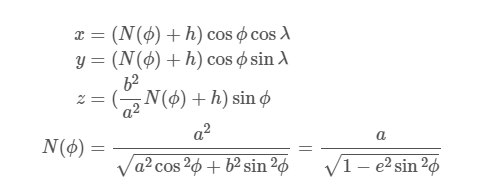
where a and b are the radii of the long axis and short axis of the Earth, respectively.
When calculating the distance between two points expressed in latitude and longitude, the distance calculated is not the shortest distance between two points, but the shortest distance between two points along the Earth’s surface (Great-circle distance) because the Earth’s surface is a curved surface is taken into account, and the calculation formula is
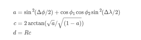
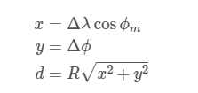
where R=6371000 is the radius of the Earth, and ϕ,λ are the latitude and longitude of the two points, respectively. To be less demanding in terms of accuracy, the equation can be simplified as
Projection coordinate system
Since the Earth’s surface is curved, it is not convenient to calculate the distance between two points along the Earth’s surface for both ECEF and LLA coordinate systems, so it is often necessary to project the Earth onto a 2D plane for visualization and map positioning, so the concept of projection coordinate system is introduced. Two types of projection coordinate systems are presented here.
Universal Transverse Mercator Projection UTM
The UTM coordinates divide the Earth into 60 longitude and 20 latitude zones. The following figure shows.
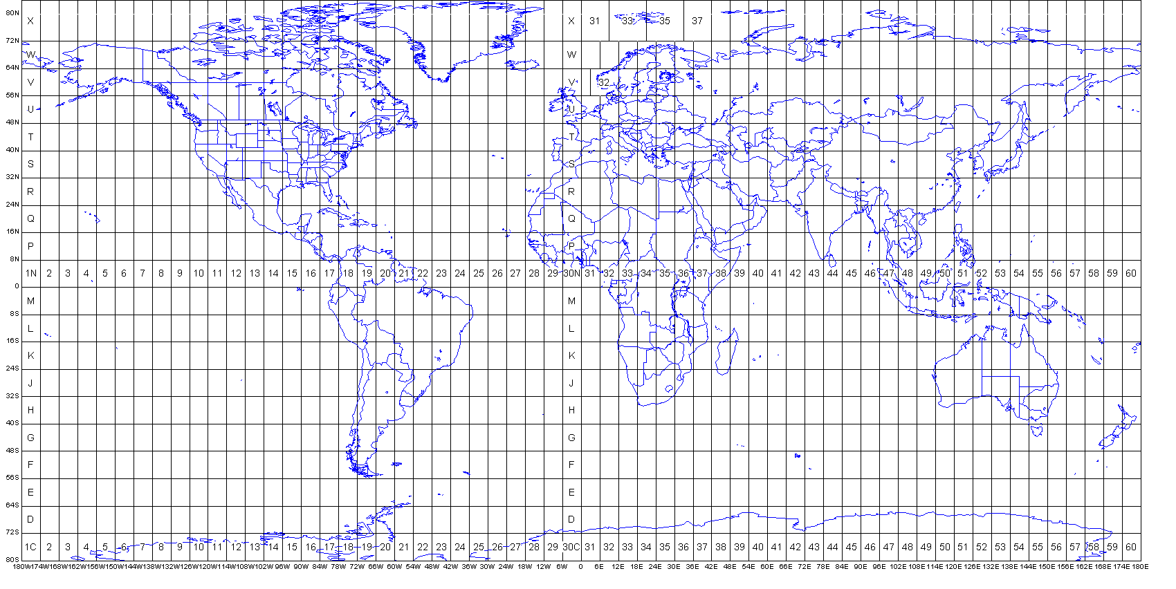
In the UTM system, each point on the Earth can be located by four parameters: the longitude band number, the dimensional band number, the distance of the point from the projection of the central meridian of that longitude zone, and the distance of the point from the projection of the equator.
Web Mercator Projection Web Mercator
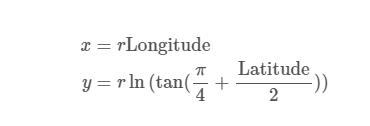
Web Mercator is capable of projecting latitude and longitude as two X/Y coordinates. The computational relationship is
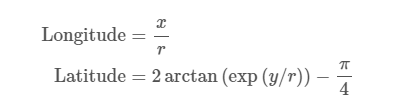
The inverse projection relationship is
Flow relationships between sensor data
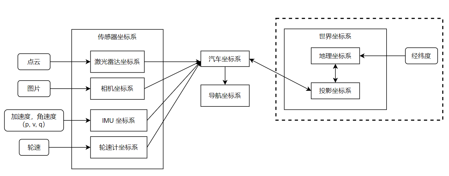
In general, the relationship between different coordinate systems for a typical positioning and map building scenario situation is as follows.
Sensor data (e.g. LIDAR, camera, etc.) are obtained as measurements in their own coordinate system, including state measurement sensors (e.g. IMU, tachometer) which also measure based on their own state (although in general it can be assumed that the state of these sensors is the same as the state of the car itself considering that the IMU and encoder are solidly connected), so it is necessary to transform these measurements into measurements in the car coordinate system by external reference.
After the sensor data is unified to the car coordinate system, the state of the car in the reference coordinate system (positioning) can be obtained by different fusion methods compared to the global measurement data (under the navigation coordinate system or under the world coordinate system), and the environmental data measured by the sensors is updated to the reference coordinate system (building map) to complete the overall process. In the case of absolute position measurement (latitude and longitude), it is generally converted to the projection coordinate system first for the convenience of calculation, and the same is passed to the car coordinate system by external reference, and the other sensor data are fused, and the position after the fusion is completed is also passed through the opposite process to finally obtain the latitude and longitude data under the geographic coordinate system.
In the absence of absolute measurements, the navigation coordinate system can be used as the reference coordinate system. When absolute measurements are available, the navigation coordinate system is generally used as a tool to calculate distances, angles, etc. between surrounding features, which is more convenient to calculate than the projected coordinate system.