Bypass routing is a homelab common requirement, the main route with hard routing to ensure stability, such as using Mikrotik’s RouterOS router as the main route, bypass routing using OpenWrt as a soft route to achieve advanced features such as ad filtering and tunneling, these functions are often not hardware accelerated and need to consume a lot of CPU to complete, x86 high performance soft routing is a very suitable choice. It can reduce one NAT on the bypass route (for IPv4 only), improve the rate, and facilitate the management of the primary route than using secondary routes.
In this paper, we propose a special bypass routing scheme that is somewhat practical in addition to the whole live, or it can also be called a secondary routing scheme for IPv4 without NAT.
Environmental information in this paper.
- RouterOS for the primary route and OpenWrt for the bypass route, requiring the primary route to have three network ports (easily satisfied for hard routes) and the bypass route to have at least two network ports, assuming they are both Gigabit ports.
- In order to use IPv6 secondary routing, the IPv6 prefix given by the operator needs to be at least /63.
- (the common /56 and /60 can be satisfied, but if /64 is given, although it might be functional, it requires different settings)
- Primary intranet (fully functional) segment: 192.168.10.0/24, secondary intranet (standby/directly connected) segment: 192.168.88.0/24
0x01 Traditional Bypass Routing Setup
The traditional bypass routing setup is only for IPv4, and the bypass router only needs a network cable to connect the LAN of the intranet and the bypass router, and the WAN of the bypass router is vacant. The IP of the LAN port of the main route is 192.168.10.1/24, and the IP of the LAN port of the bypass router is 192.168.10.2/24. Set the gateway to 192.168.10.2 in the intranet DHCP server settings (the DHCP server can run on the main route or the bypass router, but there can only be one), and then set the gateway in the bypass router to 192.168 .10.1.
This way all clients will use 192.168.10.2 as the gateway and send the egress IP packets to the bypass route, which will forward these packets because it has ip_forward turned on (routers will all have it on): since 192.168.10.1 is set as the gateway on the bypass route, the bypass route will then forward these packets directly to 192.168.10.1 on the main route (the key to traditional bypass routing is that, because it is LAN to LAN forwarding, it will not match the LAN to WAN masquerade rules in the firewall, that is, it will not perform what we often call router NAT). Since the packets are forwarded on the bypass, the tunneling software can process these packets through the rules in the firewall NAT table (e.g. redirect and tproxy) to meet our needs using bypass routing.
During the backhaul (download) of the general link, the target IP of the ingress packet after the main route NAT is the client’s intranet IP, which reaches the client directly through the switch without going through the bypass route, so it is theoretically possible to run a full two-way gigabit to the external network.
0x02 Problems with traditional bypass routing
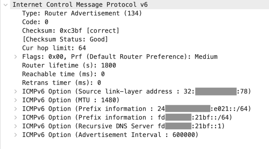
The first problem is IPv6. IPv6 does not have a separate gateway option for SLAAC (so far Android only supports SLAAC, not DHCPv6), if a machine does RA (route announcement) and lets the client get the prefix, then the client will consider it as the gateway. Since the public IPv6 prefix is obtained by PPPoE, it is inevitably the primary route that does the RA, and it automatically becomes the IPv6 gateway for all clients, and it is not possible to specify the bypass route as the gateway again.
On the other hand, IPv6 requires all devices (Nodes) to choose between the roles of Router and Host, and bypass routing is exactly one device that acts as both Router and Host.
In fact, there is no need to use bypass routing for IPv6, as IPv6 does not normally use NAT, and all the router does here is just forwarding, so we can safely use IPv6 secondary routing.
Another issue is the gigabit bottleneck, which only exists for non-directly connected traffic (e.g. tunnel traffic), i.e. traffic that goes through the tunnel, the speed of the upstream and downstream total cannot exceed 1Gbps, because the tunnel traffic backhaul also needs to go through the bypass route. For directly connected traffic, as described in the first section of the article, there is no gigabit bottleneck because the return trip does not need to go through bypass routing, so the sum of upstream and downstream speeds can reach 2Gbps, i.e., run full. However, this problem usually does not bring impact (what public network tunnel can gigabit peering), but it would be good if it could be solved together.
0x03 This article’s magic second-level routing solution
To avoid confusion, we will use “soft route” to refer to our original logical bypass route (i.e. the soft route of the OpenWrt)
This is a dual-port, IPv4 bypass + IPv6 secondary routing scheme, which is actually closer to standard secondary routing, but with some magic changes to make IPv4 into bypass mode.
The topology is as follows.
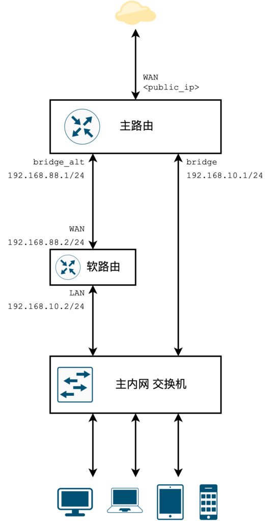
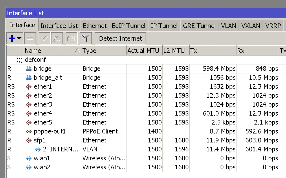
The bridge of primary route in the figure represents the primary intranet with advanced features provided by the soft route; bridge_alt represents the secondary intranet, which is only used for communication between the soft route and the primary route and can also be connected to a switch as a direct/standby intranet, which does not have the advanced features provided by the soft route, but can continue to provide standard (direct) connectivity in case of soft route failure of Internet access. If the secondary intranet does not need to be extended on the primary route, a bridge may not be created for the secondary intranet and an interface may be used instead.
Only the parameters for the IPv4 portion are listed here. the IPv6 portion is the same as the standard IPv6 secondary route, but note that the IPv6 RA and DHCP Server should run on the bridge_alt interface (see below).
If your primary route has a hardware switch and many unused ports, you can omit the “primary intranet switch” so that the bypass route is connected to the primary route via two wires, but does not form a loop.
The following is a detailed description of the IPv4 configuration.
On the primary route, based on the factory settings of the router mode (e.g. Home AP Dual, etc.), make the following changes:
-
first create a new Bridge with the name “bridge_alt”.
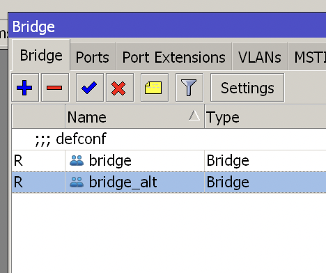
-
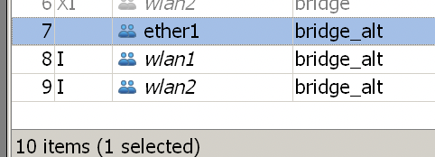
Add the required interfaces to bridge_alt, here I added the two wlan’s that come with the machine as backup network hotspots in addition to the necessary wired port ether1 (the main intranet wlan is provided by a separate AP).
-
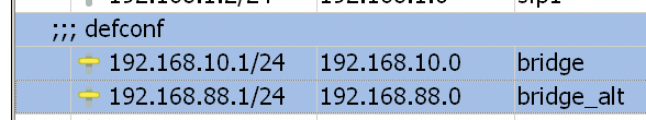
set IP for bridge: 192.168.10.1/24; set IP for bridge_alt: 192.168.88.1/24.
-
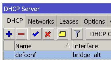
set the DHCP server for bridge_alt to assign 192.168.88.0/24; if the primary intranet is also provided with DHCP service by the primary route, set the DHCP server for bridge to assign 192.168.10.0/24 and set the gateway to 192.168. 10.2 (not shown in the figure below).
-
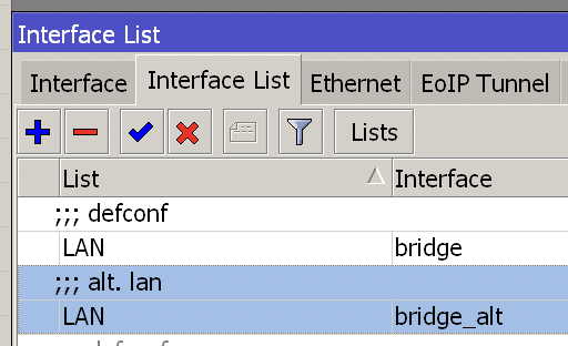
In the Interface list, set bridge_alt to LAN.
Then connect the soft route WAN port to the interface of bridge_alt via a network cable (ether0 in this article), then you should see the WAN port of the soft route getting the IP from the main route.
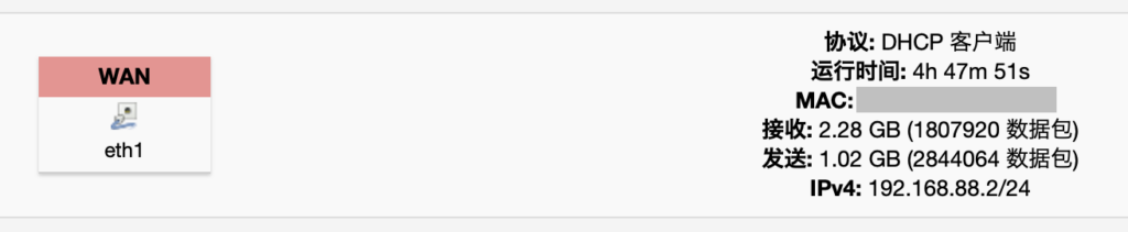
-
(You may be wondering: isn’t this the state of the secondary route? Don’t worry, we’ll turn off its NAT below)*
Here we set it up in the soft route (similar, based on OpenWrt’s default settings) :
-
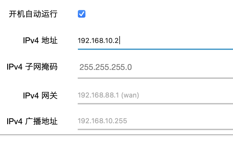
-
set the soft route’s LAN port IP to 192.168.10.2; if the DHCP service of the primary intranet is set on the primary route, turn off the DHCP service of the soft route LAN (not shown in the figure below)
-
the most critical step, to the firewall to turn off the WAN area of the “IP dynamic masquerade”, that is, masquerade, that is, we often say NAT.
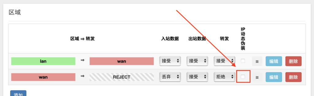
Then you will connect soft route’s LAN, primary route’s bridge and primary intranet’s device to the switch according to the topology diagram, and the IPv4 setup is done.
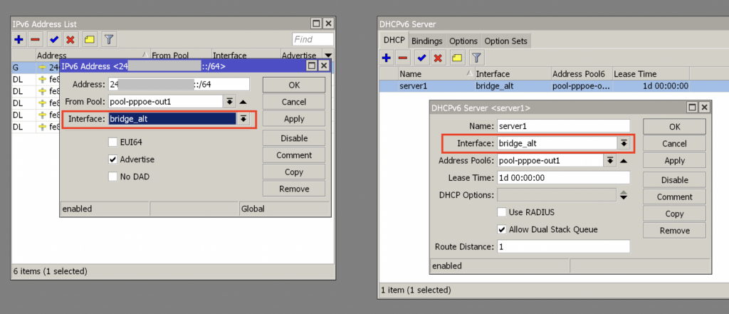
About IPv6 configuration, it is similar to the standard IPv6 secondary route, only the interface settings of RA and DHCPv6 Server are different, there are very many good tutorials on the Internet for this part, for example: https://wu.renjie.im/blog/network/ros-dhcpv6/zh-cn/, the following only write out in this article Here are only the points that need attention in this article.
On the primary route, IPv6 address settings (RA is included) and DHCPv6 settings need to be set on and only on the bridge_alt interface, and should not have any settings on bridge. In other words, under IPv6, the primary route will not use the primary intranet bridge , bridge’s IPv6 RA and routes are entirely handled by soft routes, and bridge acts as a subordinate route to bridge_alt, forming a standard IPv6 secondary route.
0x04 Postscript
The biggest difference between the method in this article and normal L2 routing is actually that for IPv4: ① the LAN-to-WAN masquerade NAT is turned off on the L2 router (the soft route in this article); ② the LAN of the L2 route is connected on the primary route. Thus, a bypass routing-like effect is achieved (bypass routing is all about one less layer of NAT).
As for why we can turn off NAT on the secondary router, think about why we need NAT on the router: if we have a normal router connected to a higher-level network and turn off NAT, then the packets we send can actually still be sent to the remote server normally, but since the source IP address in the packet is still our client’s intranet IP address, it can’t respond to us via our internal IP address to respond to us (in fact, it is usually not accepted directly by the firewall of the remote server). And masquerade NAT is a special kind of src nat, which will always use the router’s local address as a replacement for the source address of the IP packet, thus allowing the response packet from the remote server to be sent correctly to the router, which will then forward it to the client.
But in the method of this article, first of all, after our packets are forwarded directly to the primary route through the secondary router, the response packets from the remote server will reach the primary route normally because the primary route is with NAT, and then when the primary route forwards the response packets, the response packets can be sent directly to the client without going through the secondary router because we have configured the above ②, so that the NAT of the secondary router is not needed, and a round-trip communication is completed normally.
Finally, the methods in this article are more whole-live oriented. There is nothing wrong with using a single route directly, or a normal secondary route, or even using traditional bypass routing and turning off IPv6 (after all, in 2022 ISPs and CDNs are still optimizing for IPv4, and many places are still “turning off IPv6 to improve the Internet experience”). However, one of the joys of homelab is to toss around various non-standard solutions and configurations, and this article also proposes a bypass routing + normal IPv6 solution.