TUN is a Layer 3 virtual network device provided by the kernel and implemented by software to replace the real hardware. It is equivalent to opening a port at the Layer 3 (network layer) location of the system network stack and handing over the eligible (route matching) Layer 3 packets to the corresponding user space software for processing, and the user space software can also inject packets into the system network stack through the TUN device. It can be said that the TUN device is a channel between the user space software and the system network stack.
TAP is a Layer 2 (Ethernet) virtual network device that handles Ethernet frames, and more information is available at a lower level, but is out of the scope of this article.
If we want to do something with TUN, we actually have to write a user-state program that gets a TUN device handle, writes serialized IP packets to it, reads the data from it and reduces it to IP packets for processing, and if necessary, needs to remove its payload to continue parsing it into the appropriate transport layer protocol.
It is VPN and proxy programs that typically use TUN technology, however, these two types of programs typically have different behaviors when dealing with IP packets passed in TUNs.
- VPN typically does network layer encapsulation: the IP packet is obtained, encrypted and encapsulated, and then transmitted over some connection to another network, to which it is sent after being decapsulated and decrypted. In this process, the modifications to the IP packet itself are very small and do not involve changes to the overall structure, usually only the source and destination IPs are modified and NAT is done.
- The proxy is usually a proxy for the transport layer: after getting the IP packet from the TUN device, it needs to continue to parse the payload, restore the TCP or UDP structure, and then encrypt and encapsulate the transport layer (TCP or UDP) payload. The network layer IP and transport layer port information is typically handled as metadata for that connection, using additional encryption and encapsulation.
In short, VPNs do not need to parse IP packet payloads, while proxies need to parse out and process transport layer information, especially for complex protocols such as TCP, which requires great care and rigor. If we use TUN technology, there are usually two modes for proxy programs: implementing the network stack in the user state, or directly using the OS network stack.
User State Network Stack
The first option is to implement the network stack in the user state, which is not a small project, especially the implementation of the TCP protocol, because its protocol is very complex, there are many details to pay attention to, so their own implementation is very easy to make mistakes. So we generally look for ready-made implementations to use, there are a lot of mature and efficient implementations, I believe it must be orders of magnitude better than what I wrote myself.
Network stack implementation
- If you use C language, lwIP is a very good choice, open source by the Swedish Institute of Computer Science Academy, it is a lightweight TCP/IP stack implementation that implements full TCP, is widely used in embedded devices, and stability is guaranteed. Also, lwIP has bindings for many other languages, including go and rust, which allows us to choose lwIP as a user-state network stack implementation when developing in other languages as well.
- If one chooses to develop a user-state application for TUN using the Go language (which is actually the choice of most people), one can choose the implementation in Google’s open source gVisor. The purpose of the gVisor project is to provide its own application kernel for containers, where the tcpip implementation is backed by Google and quality is guaranteed.
- If we choose to use Rust for development, our choice is a bit more difficult, there is no weathered, time-tested implementation, and after extensive comparison I recommend smoltcp, which is a standalone, event-driven TCP/IP implementation for bare-metal real-time systems. This is a standalone, event-driven TCP/IP stack developed for bare-metal real-time systems, designed for simplicity and robustness, and should be trusted.
- Of course, I think another implementation to look forward to is Google’s Netstack3 for the Fuchsia OS , previously implemented by Go, but now Google has re-implemented a new one in Rust, with Google’s endorsement, so you can look forward to it.
Usage flow
After looking at the available implementations, let’s look at how the network stack is used in the user space implementation. Although each library has different programming interfaces and usage methods under different implementations, the basic idea is the same, so we will only discuss the basic usage flow here.
Basic idea
In principle, the user-state network stack is to continuously parse the payload data in the TCP stream from the IPv4 packets through protocol parsing; the transport layer payload is continuously encapsulated through the protocol to get the final IPv4 packets.
Read out from TUN
A sequence of bytes read from the handle corresponding to the TUN device is the IP packet that needs to be processed, usually for the IPv4 protocol, but it still needs to be judged based on the first byte of the byte sequence first.
If it is determined to be an IPv4 packet, the whole byte sequence is thrown into the Packet Parser implementation of IPv4 and the IPv4 packet structure is restored. Based on the protocol field in IPv4 Header, determine which upper layer protocol the payload should use to parse. rfc791
Generally, we only need to deal with ICMP, TCP and UDP protocols, take TCP as an example, we just need to throw the IPv4 payload into TCP’s Parser to get the transport layer load we want. (In reality, it’s not as simple as that)
Write data to TUN
The write process is actually the reverse of the read process, where you get the payload of a transport layer protocol.
Next, we build the IPv4 Header and stitch the UDP packet into the IPv4 payload. Once you have the IPv4 packet, you can serialize it into a byte sequence and write it to the TUN handle.
Practical Use
The above read and write process looks simple, but in practice there are many things to consider, including but not limited to fragmentation, packet loss, retransmission, traffic control, etc. TCP is an extremely complex transport layer protocol with many scenarios to consider, so obviously using the above basic idea is very cumbersome and difficult to use.
Many user-state network stacks certainly take this into account, and implementations provide a very friendly and straightforward interface that allows you to create a TCP/IP network stack instance directly and get two handles, one for reading and writing network layer IP packets, and the other for receiving and writing transport layer loads, with all the complex conversion relationships and special cases in between shielded internally.
OS network stack
For our needs, we are actually converting between IPv4 and TCP payload, which is exactly what the OS network stack does. We can’t simply use the OS network stack code directly, but we can find a way to reuse the functionality provided by the OS network stack. TUN has already opened a port at the network layer, but we need to open a port at the transport layer, so we can use the socket provided by the operating system.
We use the socket provided by the OS to create a transport layer Listener, modify the target IP and target port of an IPv4 packet to the IP and port we are listening to, and then inject the IPv4 packet into the OS network stack through the TUN, and the OS will automatically parse it accordingly and send the required transport layer payload to the Listener. The OS will automatically parse the packet accordingly and send the required transport layer payload to the Listener via the socket created earlier, thus completing the “read out” operation using the OS network stack.
For the “write in” operation, you only need to write to the transport layer connection handle you just created, and the OS network stack will also perform the corresponding packet sealing to form the IPv4 packet. Obviously, the reverse packet needs to be considered. When writing to the transport layer connection handle and the OS network stack seals the packet, the source IP and source port will be considered as the new target IP and target port, because we need to make the returned IPv4 packet available for capture by the TUN interface. The source IP should be restricted to an IP in the TUN segment.
Workflow
When utilizing the OS network stack, the following steps are usually followed, here is an example of TCP protocol.
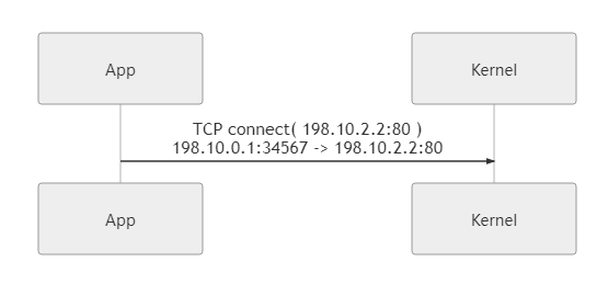
In our example, the TUN network is configured with 198.10.0.1/16, the host IP is 198.10.0.1, the proxy client listens to 198.10.0.1:1313, the app wants to access google.com:80, and the custom DNS service returns the Fake IP of google.com 198.10.2.2 .
-
Proxy Creating TCP Socket Listener
The first step here is to open a port in the transport layer of the system network stack and create a TCP Socket Listener that listens to
198.10.0.1:1313. -
An App initiates a connection
When an app that needs a proxy initiates a connection to
google.com:80, we return a Fake IP (198.10.2.2) via a custom DNS service to route the traffic to the TUN device.Of course, you can also capture traffic without using the Fake IP method. You can also direct traffic to the TUN device by configuring routing rules or traffic redirection, but Fake IP is the most common method, so it is used as an example here.
-
Parsing the IPv4 read by the TUN into TCP load data
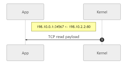
After the TUN device captures the traffic, that is, IPv4 packets, and reads them out, it needs to use the system network stack to parse out the TCP load data.
In this step, the read IPv4 packet needs to be modified, that is, the source IP, source port, destination IP and destination port as we mentioned above, and the corresponding checksum also needs to be recalculated. The purpose of the modification is to make the IPv4 packets injected into the OS network stack via TUN to be correctly routed and return the innermost TCP payload to us via the TCP socket we are listening to at the beginning.
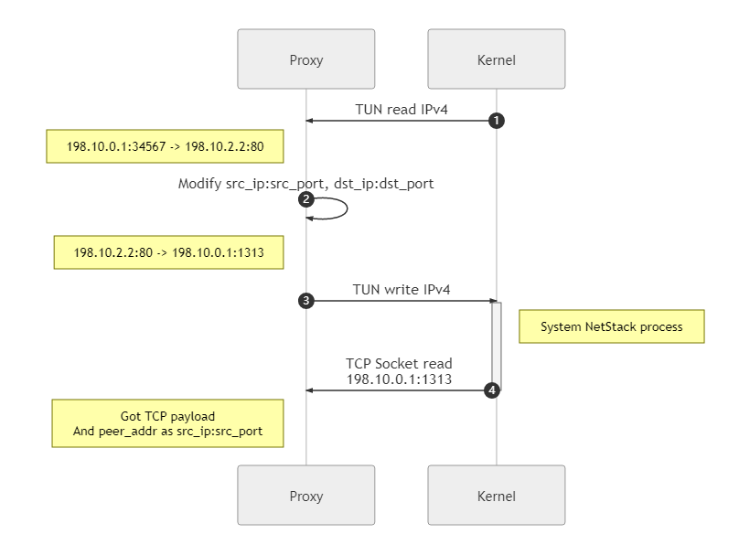
Here, for convenience, the source IP and source port are set directly to the initial target IP and target port, and there are more setup policies, or NAT policies, for actual programming.
-
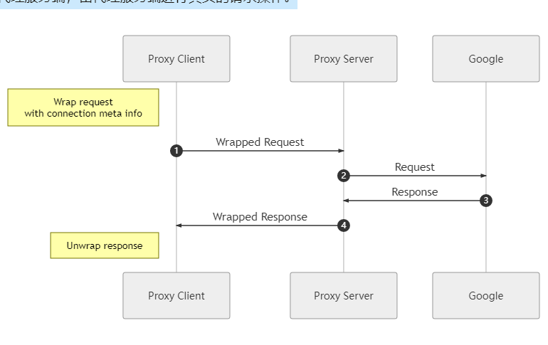
Proxy client requesting proxy server
At this point, the proxy client has already got the real TCP payload of the request, and can get the source IP and source port modified in step 3 by getting the peer information of the TCP connection, through which it can get the IP and port that the App really wants to access by checking the NAT table (or even get the domain name information by checking the DNS request record), so the proxy client can encrypt and encapsulate according to its own Therefore, the proxy client can encrypt and encapsulate the information according to its own protocol, and then send it to the proxy server, which will perform the real request operation.
-
Packetize return data back to IPv4 and write to TUN
Through the communication between proxy client and proxy server, proxy server and Google, we get the real return data from Google, now we need to re-encapsulate the IPv4 packet, or use the system network stack: write the data to TCP socket (
198.10.0.1:1313), then we can get the encapsulated IPv4 on the TUN side, it’s that easy.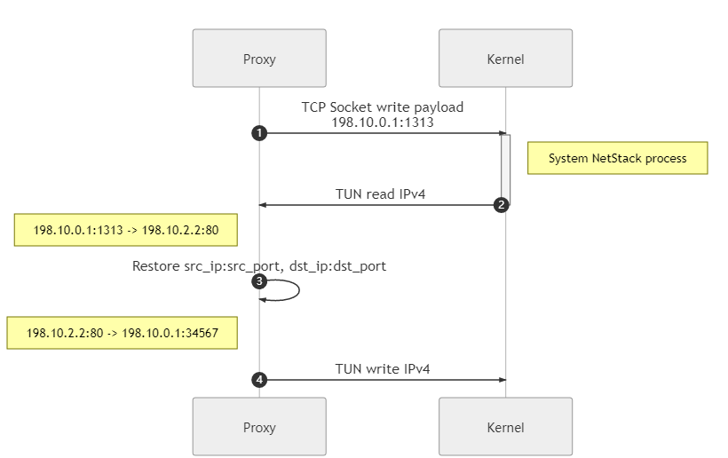
-
App gets the return data
The above process is how the IPv4 to TCP load data and its reverse direction transformation is done using the OS network stack. With this approach, it is possible to take full advantage of operating system implementations that are well-tested, reliable, and meet a variety of complex situations. However, there are drawbacks in that the data needs to be copied multiple times, increasing performance loss and latency.
NAT Policies
You can of course implement different NAT types to meet a variety of needs, but that is a more in-depth topic and not discussed in this article.
In step 3 of the process, you should have noticed that there are restrictions on the source IP and source port modification. We need to restrict the IP to the TUN segment so that the returned packets can be recaptured by the TUN device. But this restriction is very loose, and in our example configuration of the TUN device segment, you have 2^16 IPs to choose from, and 2^16 ports to choose from for each IP.
But if you look closely, you will see that the above example does not take full advantage of these resources, we just use the Fake IP as the source IP, the real target port as the source port, and all the other ports of this IP are left unused. Also I have found in some programs written by others that they choose only one IP to set as the source IP and by reasonably assigning the port of that IP as the source port, in this case the rest of the IP resources in the TUN segment are wasted.
The above two NAT policies are fine for personal computers, but if the proxy client is running on a gateway and the number of IPs accessed in the network exceeds the maximum number of IPs in the segment, or the number of hash(ip:port) exceeds the total number of ports (2^16), it will be difficult to continue assigning NAT entries. Therefore, we should write a special NAT management component to allocate IP and port resources reasonably to maximize utilization.
Prevent Loops
Facts aside, if we want to proxy all traffic, it is the intuitive and plain idea of directing all traffic to our TUN device via routing rules, as simple as the following command.
|
|
If you do write that, you’ll find that you can’t get on the Internet. This is because there is a loop.
If you think about it a little bit, you will find that although we want to proxy all traffic, the traffic between the proxy client and the proxy server is something that needs to be skipped, and if you use the above route, it will cause the traffic from the proxy client to go through the route and then from the TUN back to the proxy client, which is a dead loop, and no traffic can go out. The traffic is only near and not out, spinning back and forth, your file open count explodes, the OS stops assigning you more handles, data is copied back and forth, your CPU fan spins hard, and your computer starts to get stuck.
This is something we don’t want to see and need to take some measures to avoid loops. In practice there are quite a few ways to avoid this, for example by configuring routing rules in a reasonable way so that the traffic connecting to the proxy server can be matched to the external network interface without any problems. However, this method is not flexible enough, and if the proxy server IP changes, you need to change the routing rules in time, which is very troublesome, so we will introduce other methods.
Fake IP
Fake IP is the method we used in the above example, which is a way to restrict incoming traffic. The basic idea is to implement a DNS server that returns a fake IP address for user queries, and we can restrict the returned IP address to the network segment of the TUN device, so that the traffic initiated by the application is actually the traffic sent to the TUN network and is naturally routed to match, without routing the entire traffic as before, and the rest of the traffic, including requests initiated by proxy clients, will not be The rest of the traffic, including requests from proxy clients, will not be routed, ensuring that no loops are created.
When the proxy client needs to know the address that the application really wants to request, it can do a reverse lookup to the DNS server it implements through some interfaces.
Policy Routing
From the previous analysis, we can find that the loop is caused by the traffic from the proxy client itself being routed to the TUN device, so we can find a way to make the traffic from the proxy client itself go out of the real physical network interface instead of the TUN.
In a (Unix-like) system, the traffic from the proxy client can be marked with the fwmark firewall, and then the marked traffic can be routed through a separate routing table via policy routing, thus bypassing the global traffic capture.
cgroup
cgroup is a Linux kernel feature that can be used to restrict and isolate resources from processes, where the net_cls subsystem can restrict access to the network. At the network control level, class ID can be used to determine if traffic belongs to a certain cgroup, so traffic from a specific cgroup can be fwmarked so that it can be controlled by policy routing.
We can create a cgroup for bypassing proxies and use the default routing rules for traffic from processes under that cgroup, while traffic from the rest of the processes that are not in that cgroup are routed to the TUN device for proxying.
Some other knowledge
Difference between TUN and TAP
TAP is at layer 2, the data read and written needs to be in an Ether frame structure.
TUN At layer 3, the data read and written needs to be in IP packet structure.
IP and other configurations
When configuring IP for the NIC, you are actually modifying certain parameters in the kernel network stack, not the NIC. Although the NIC will also have some configuration items that can be modified, in general the case is modified by other methods (drivers).
Difference between physical NIC and virtual NIC
A physical NIC will have DMA capability, when DMA is enabled the communication between the NIC and the network stack (buffers in memory) is managed by the DMA controller, resulting in higher performance and lower latency.
How to create a TUN device
Under Linux everything is a file, /dev/net/tun is a special character (char) device file, which is opened to get a file handle and then configured with the ioctl() system call. Here you can choose whether to open a TUN device or a TAP device, and you can set the device name.
See: Network device allocation
Relationship to BPF
BPF is an advanced packet filter that can be attached to an existing network interface, but does not provide a virtual network interface itself. The TUN/TAP driver provides a virtual network interface to which BPFs can be attached.