Overview
IPv6 is called Internet Protocol Version 6, but although it is called Version 6, it is actually the second generation standard protocol of network layer protocol. The main reason for its emergence is to solve some shortcomings of IPv4 in practical application scenarios.
Comparison of advantages and disadvantages with IPv4
| Issues | IPv4 Defects | IPv6 Advantages |
|---|---|---|
| Address Space | IPv4 addresses are only 32 bits, so the total number of addresses that can be represented is about 4.3 billion. The distribution of IP addresses is also very uneven for historical reasons: the United States accounts for about half of the global address space, while Europe is relatively scarce, and the Asia-Pacific region is even scarcer.The methods used in IPv4 to address the address shortage are CIDR and NAT, but both have their own drawbacks. | IPv6 has 128 bits. Theoretically, a total of 4.3 billion x 4.3 billion x 4.3 billion x 4.3 billion addresses can be supported. |
| Message format | The IPv4 header contains optional options for Security, Timestamp, Record route, etc. These options can expand the length of an IPv4 header from 20 bytes to 60 bytes. IPv4 messages carrying these Options often require software processing by intermediate routing and forwarding devices during forwarding, which is a significant performance drain and therefore rarely used in practice. | Compared with IPv4, IPv6 removes the IHL, Identifier, Flag, Fragment Offset, Header Checksum, Option, and Paddiing fields and adds only the stream tag field, thus simplifying the processing of IPv6 headers compared with IPv4 and improving the processing efficiency. In addition, IPv6 introduces the concept of extended headers to better support the processing of various options, so that new options can be added without modifying the existing structure, which is theoretically infinitely scalable, reflecting the excellent flexibility. |
| Automatic configuration and reprogramming | Because IPv4 addresses are only 32 bits long and are unevenly distributed, IP addresses often need to be reassigned during network expansion or redeployment, so automatic configuration and re-addressing is needed to reduce maintenance efforts. The current IPv4 auto-configuration and re-addressing mechanism relies on the DHCP protocol. | The IPv6 protocol has built-in support for automatic address configuration to enable hosts to discover the network and obtain IPv6 addresses automatically, greatly improving the manageability of the internal network. |
| routing aggregation | Due to allocation planning issues in the early stages of IPv4 development, many IPv4 addresses were allocated incoherently and routes could not be aggregated efficiently. The increasingly large routing tables consume a lot of memory and have an impact on device costs and forwarding efficiency, which has prompted device manufacturers to upgrade their products to improve route addressing and forwarding performance. | The large address space makes IPv6 easy to deploy in a hierarchical network. The hierarchical network structure allows for easy route aggregation and efficient route forwarding. |
| End-to-end security | The IPv4 protocol was not carefully designed for security, so the inherent framework structure does not support end-to-end security. | In IPv6, the network layer supports IPSec authentication and encryption, supporting end-to-end security. |
| QoS | With the rapid popularity and use of web conferencing, VoIP, and Internet TV, customers are demanding better QoS to guarantee real-time forwarding of these audio and video. IPv4 does not have a dedicated means to support QoS. | IPv6 adds flow marking domains to provide QoS guarantees. |
| Support for mobile features | As the Internet evolves, mobile IPv4 has some problems, such as triangular routing, source address filtering, etc. | The IPv6 protocol mandates support for mobility. Compared with mobile IPv4, mobile IPv6 uses the neighbor discovery function to directly discover and obtain forwarding addresses from the foreign network without using a foreign proxy. At the same time, using the route extension header and destination address extension header, mobile nodes and peer nodes can communicate directly with each other, solving the delta routing and source address filtering problems of mobile IPv4, making mobile communication more efficient and transparent to the application layer. |
IPv6 address
Representation
IPv6 has a total of 128 bits, which are represented by 4 hexadecimal numbers by dividing them into 8 groups of 16 bits each. Each group is separated by a colon. For example: FC00:0000:130F:0000:0000:09C0:876A:130B. To facilitate writing, some compressed write-ups are provided.
- The prefix 0 can be omitted. so this address can also be written as:
FC00:0:130F:0:0:9C0:876A:130B. - The address contains two or more consecutive groups that are all zeros, which can be replaced by a double colon “::”. So it is further abbreviated as:
FC00:0:130F::9C0:876A:130B.Note, however, that there can be only one “::” in an IPv6 address, because if there are more than one, it is impossible to identify how many sets of zeros each “::” represents.
Address structure
Similar to the IPv4 design, an IPv6 address is composed of two parts.
- Network prefix: n bits, which is equivalent to the network number in IPv4.
- Interface identifier: 128-n bits, equivalent to the host number in an IPv4 address.
Address classification
IPv6 addresses are classified into unicast addresses, anycast addresses, and multicast addresses. Compared with IPv4, broadcast addresses are eliminated and replaced by richer multicast addresses, and multicast addresses are added.
unicast address
A unicast address is used to represent the address of one network interface of a node. The following types of unicast addresses are available.
| Type | Description |
|---|---|
| Unspecified address | means ::/128. This address indicates that the Acura interface or node does not yet have an IP address. |
| Loopback Address | This refers to ::1/128, which is the same as 127.0.0.1 in IPv4 |
| Global unicast address | Similar to a unicast address in IPv4. Consists of a global routing prefix (at least 48 bits) + a Subnet ID + an Interface ID. The global routing prefix is assigned by the provider to an organization, and thus can also serve as an aggregated route. |
| Link Local Address | A link-local address is a restricted address type in IPv6 that can only be used between nodes connected to the same local link. It uses a specific local link prefix FE80::/10 (with a maximum 10-bit value of 1111111010), while adding the interface identifier as the lower 64 bits of the address. When a node starts the IPv6 stack, each interface of the node is automatically configured with a link-local address (its fixed prefix + the interface identifier formed by the EUI-64 rule) at startup. In IPv4, the link-local address is 169.254.0.0/16 |
| Unique local address | A unique local address is another type of address that is limited in application and can only be used within a site. Due to the repeal of local site addresses (RFC 3879), unique local addresses are used in place of local site addresses. The role of a unique local address is similar to that of a private network address in IPv4, and any organization that has not applied for a provider-assigned global unicast address can use a unique local address. A unique local address can only be routed and forwarded within the local network and not across the global network. The fixed prefix of the unique local address is FC00::/7, which is represented in binary as 1111 110. |
Anycast Address
An anycast address is generally used to represent an interface on a set of nodes, and when a packet is sent to an anycast address, the intermediate routing device sends the packet to the interface on the nearest node. Therefore, it can be seen that anycast addresses are designed to provide redundancy and load balancing functions when multiple hosts or nodes provide the same service. However, in practice, anycast addresses can only be assigned to routing devices, not to hosts and other devices. And the anycast address cannot be used as the source address of IPv6 messages.
There is no separate address space for anycast addresses, and they use the same address space as unicast addresses.
Multicast Address
Multicast for IPv6 is the same as IPv4 and is used to identify a set of interfaces, which generally belong to different nodes. A node may belong to zero to multiple multicast groups. Messages sent to a multicast address are received by all interfaces identified by the multicast address. For example, multicast address FF02::1 indicates all nodes in the local range of the link, and multicast address FF02::2 indicates all routers in the local range of the link.
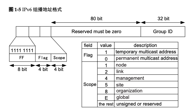
An IPv6 multicast address consists of four parts: a prefix, a flag field, a scope field, and a multicast group ID:
- Prefix: The prefix of an IPv6 multicast address is FF00::/8.
- When the value of this bit is 0, it means that the current multicast address is a permanent address assigned by IANA; when the value is 1, it means that the current multicast address is a temporary multicast address (not a permanent address).
- Scope field (Scope): 4 bits in length, used to limit the range of multicast data streams sent in the network, the corresponding relationship between the value and meaning of this field is shown in Figure 1-5.
- Multicast group ID (Group ID): 112 bits in length, used to identify the multicast group. Currently, RFC2373 does not define all 112 bits as the group ID, but proposes to use only the lowest 32 bits of the 112 bits as the multicast group ID and set the remaining 80 bits to 0. This way, each multicast group ID is mapped to a unique Ethernet multicast MAC address (RFC2464).
The requested node multicast address is generated by the unicast or anycast address of the node. When a node has a unicast or anycast address, it generates a requested node multicast address and joins the multicast group. A unicast address or an anycast address corresponds to a requested node multicast address. This address is mainly used for neighbor discovery mechanism and address duplication detection function.
IPv6 does not have broadcast addresses and does not use ARP, but still requires the ability to resolve from an IP address to a MAC address. In IPv6, this function is accomplished through the Neighbor Solicitation message. When a node needs to resolve the MAC address corresponding to an IPv6 address, it sends an NS message whose destination IP is the multicast address of the requested node corresponding to the IPv6 address to be resolved; only the node with the multicast address will check the processing.
The multicast address of the requested node consists of the prefix FF02::1:FF00:0/104 and the last 24 bits of the unicast address.
IPv6 Message Format
The IPv6 message format is composed of three main parts
- IPv6 basic header: 8 fields, fixed at 40 bytes.
- IPv6 extended header: The extended header is chain structured and theoretically infinitely expandable
- Upper-layer protocol data unit: generally consists of an upper-layer protocol header and its payload, which can be an ICMPv6 message, a TCP message or a UDP message.
The basic header format of an IPv6 header is as follows.
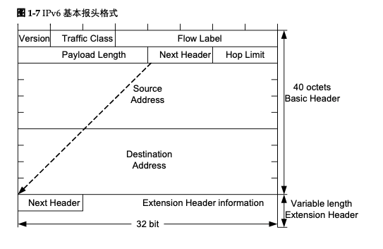
These fields are explained as follows.
- Version:Version number, 4 bits in length. for IPv6, the value is 6.
- Traffic Class: Flow class, 8 bits in length, equivalent to the TOS field in IPv4, indicating the class or priority of the IPv6 datagram, mainly used for QoS.
- Flow Label: Flow Label, 20 bits in length, a new field in IPv6, used to distinguish real-time traffic.
- Payload Length: The payload length is the rest of the datagram immediately following the IPv6 header (i.e., the extension header and the upper layer protocol data unit). This field can only represent payloads of up to 65535 bytes in length. If the length of the payload exceeds this value, the field is set to 0. The length of the payload is indicated by the Oversize Payload option in the Hop-by-Hop Option extension header.
- Next Header: The next header, 8 bits long, which defines the type of the first extension header (if present) immediately following the IPv6 header, or the protocol type in the upper layer protocol data unit.
- Hop Limit: Hop limit, 8 bits long, similar to the Time to Live field in IPv4, which defines the maximum number of hops an IP datagram can pass through. When the value of this field is 0, the datagram will be discarded.
- Source Address: The source address, 128 bits in length, indicating the address of the sender.
- Destination Address: The destination address, 128 bits long, indicates the address of the receiver.
From the above description, we know that the basic header of IPv6 is simplified compared with that of IPv4, except for the IHL, identififiers, Flags, Fragment Offset, Header Checksum, Options, Paddiing fields, and only the Flow Label field is added. This design can improve the data processing performance of routing devices.
In IPv4, the IPv4 header contains optional fields Options, which cover security, Timestamp, Record route, etc. These Options can expand the IPv4 header length from 20 bytes to 60 bytes. In the forwarding process, processing IPv4 messages carrying these Options takes up a lot of resources of the device, so they are rarely used in practice.
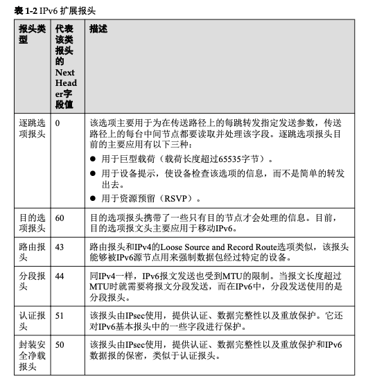
IPv6 strips these Options from the basic IPv6 header and places them in the extended header, which is placed between the IPv6 header and the upper layer protocol data unit. An IPv6 message can contain zero, one or more extension headers, with one or more extension headers added by the sender only when some special processing is required by the device or destination node. Unlike IPv4, IPv6 extension headers are arbitrary in length and are not limited to 40 bytes, making it easy to expand and add options later. However, in order to improve performance in handling option headers and transport layer protocols, extension headers are always an integer multiple of 8 bytes in length.
When multiple extension headers are used, the Next Header field of the preceding header specifies the type of the next extension header, thus creating a chained list of headers. Currently, there are six IPv6 extension headers defined in RFC 2460: hop-by-hop option header, destination option header, routing header, segmentation header, authentication header, and encapsulation security net load header.
ICMPv6
ICMPv6 (Internet Control Message Protocol for the IPv6) is one of the base protocols for IPv6.
In IPv4, the Internet Control Message Protocol (ICMP) reports errors and information to the source node about the transmission of IP packets to the destination. It defines messages for diagnostic, informational, and management purposes, such as: destination unreachable, packet overlength, timeout, response request, and response reply. In IPv6, ICMPv6 provides the common features of ICMPv4, but is also the basis for other features such as neighbor discovery, stateless address configuration (including duplicate address detection), and PMTU discovery.
The protocol type number of ICMPv6 (i.e., the value of the Next Header field in IPv6 messages) is 58.
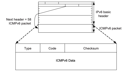
The fields in the message are explained as follows:
- Type:Indicates the type of the message, 0 to 127 indicates the error message type, 128 to 255 indicates the message message type.
- Code: indicates the type of subdivision of this message type.
- Checksum:Indicates the checksum of the ICMPv6 message.
Neighbor Discovery
Neighbor Discovery Protocol (NDP) is an important underlying protocol in the IPv6 protocol architecture. It replaces IPv4’s ARP (Address Resolution Protocol) and ICMP Router Discovery, and defines the use of ICMPv6 messages for address resolution, neighbor status tracking, duplicate address detection, router discovery, and redirection.
Address Resolution
Neighbor Discovery Protocol (NDP) is a Layer 3 protocol based on ICMPv6 that replaces the IPv4 ARP protocol. Two types of ICMPv6 messages are used in the address resolution process: Neighbor Solicitation (NS) and Neighbor Advertisement (NA).
- NS message: Type field value is 135 and Code field value is 0. It is similar to ARP request message in IPv4 in address resolution.
- NA message: Type field value is 136, Code field value is 0. It is similar to ARP response message in IPv4 in address resolution.
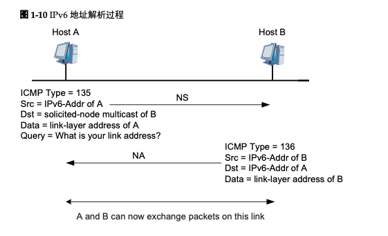
Before Host A sends a message to Host B, it must resolve the link layer address of Host B. So first Host A sends an NS message, where the source address is the IPv6 address of Host A, the destination address is the multicast address of the requested node of Host B, and the destination IP to be resolved is the IPv6 address of Host B. This means that Host A wants to This means that Host A wants to know the link layer address of Host B. It is also important to note that the link layer address of Host A is carried in the Options field of the NS message.
When Host B receives the NS message, it responds to the NA message, where the source address is the IPv6 address of Host B and the destination address is the IPv6 address of Host A (using the link-layer address of Host A in the NS message for unicast), and the link-layer address of Host B is placed in the Options field. This completes a process of address resolution.
Tracking the status of neighbors
Communication through or to a neighbor can be interrupted for a variety of reasons, including hardware failure, hot insertion of an interface card, etc. If the destination fails, recovery is impossible and communication fails; if the path fails, recovery is possible. Therefore, nodes need to maintain a neighbor table, each neighbor has a corresponding state, and the state can be migrated between.
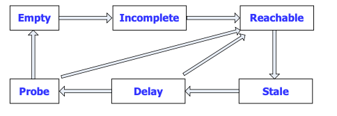
Five neighbor states are defined in RFC2461, namely: Incomplete, Reachable, Stale, Delay, and Probe.
The following is an example of the neighbor state change of node A during the mutual communication between two neighbor nodes A and B (assuming that A and B have never communicated before) to illustrate the process of neighbor state migration.
- A sends NS message first and generates cache entry, at this time, the neighbor state is Incomplete.
- If B replies to the NA message, the neighbor state changes from Incomplete to Reachable, otherwise the neighbor state changes from Incomplete to Empty after a fixed time, i.e., the table entry is deleted.
- After the neighbor reachable time, the neighbor state changes from Reachable to Stale, i.e., the reachability of the neighbor node is not determined.
- If in the Reachable state, A receives an unsolicited NA message from B, and the link layer address of B carried in the message is different from that in the table entry, the neighbor state changes to Stale immediately.
- After the STALE state reaches the aging time, it enters the Delay state.
- After a fixed period of time (5 seconds), the neighbor state changes from Delay to Probe, during which the neighbor state changes from Delay to Reachable if there is an NA answer.
- In the Probe state, A sends unicast NS every certain time interval (1 second), and after a fixed number of times (3 times), the neighbor state changes to Reachable if there is an answer, otherwise the neighbor state changes to Empty, i.e., the table entry is deleted.
Duplicate Address Detection
Duplicate Address Detection (DAD) is performed before an IPv6 unicast address is used on an interface to detect if another node is using that address. DAD detection is necessary especially when the address is autoconfigured. An IPv6 unicast address is called a Tentative Address after it has been assigned to an interface and before it passes the duplicate address test. The interface cannot use this test address for unicast communication, but it will still join two multicast groups: the ALL-NODES multicast group and the Solicited-Node multicast group corresponding to the test address.
The IPv6 duplicate address detection technique is similar to the free ARP in IPv4: the node sends an NS message to the Solicited-Node multicast group corresponding to the test address, and the target address of the NS message is the test address. If an NA message is received from another site, it proves that the address is already in use on the network and the node will not be able to use the test address for communication.
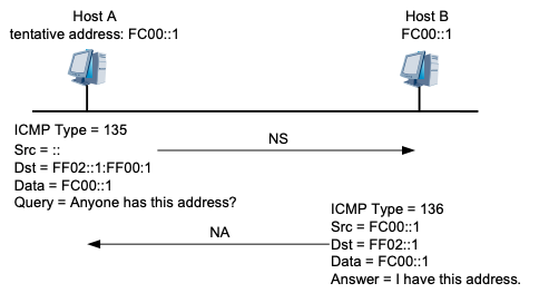
Host A’s IPv6 address FC00::1 is the newly configured address, that is, FC00::1 is Host A’s test address. Host A sends an NS message with FC00::1 as the requested destination address to FC00::1’s Solicited-Node multicast group for duplicate address detection, and since FC00::1 is not formally specified, the The source address of the NS message is an unspecified address. When Host B receives this NS message, there are two ways to handle it:
- If Host B finds that FC00::1 is a test address of its own, Host B abandons the use of this address as the interface address and does not send NA messages.
- If Host B finds that FC00::1 is an address that is already in normal use, Host B sends an NA message to FF02::1 that contains FC00::1. This message is received by Host A, which finds that its test address is a duplicate. The test address on Host A is not valid and is marked as duplicated.
Router Discovery
The router discovery function is used to discover devices connected to the local link and to obtain prefixes and other configuration parameters related to address autoconfiguration.
In IPv6, IPv6 addresses can support stateless autoconfiguration, where a host obtains network prefix information through some mechanism and then the host generates the interface identification portion of the address itself. The router discovery function is the basis of the IPv6 address autoconfiguration function, which is mainly implemented by the following two types of messages:
-
Router Advertisement (RA) message: Each device sends RA messages multicast at regular intervals in order to let hosts and devices on the Layer 2 network know about its existence, and the RA message carries network prefix information and some other flag bit information (the value of the Type field of the RA message is 134).
-
Router Request RS (Router Solicitation) message: In many cases, hosts wish to obtain network prefixes for communication as soon as possible after accessing the network, at this time, hosts can immediately send RS messages, and devices on the network will respond to RA messages (the value of the Tpye field of the RS message is 133).
Redirection
When a gateway device finds that a message is better forwarded from another gateway device, it sends a redirect message to inform the sender of the message, allowing the sender to choose another gateway device. The redirect message is also carried in an ICMPv6 message with a Type field value of 137, which carries information such as the next hop address of the better path and the destination address of the message to be redirected.
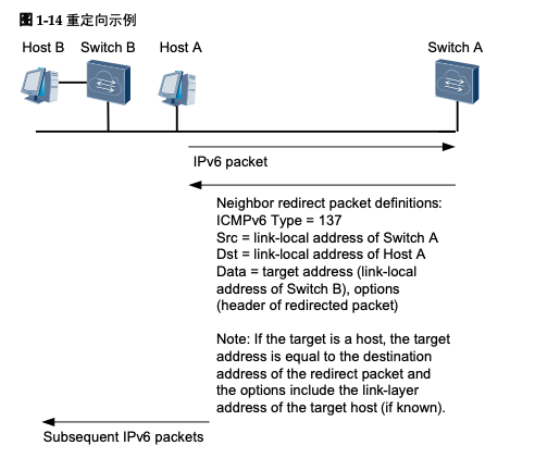
Host A needs to communicate with Host B. Host A’s default gateway device is Switch A. When Host A sends a message to Host B, the message will be sent to Switch A. Switch A receives the message from Host A and finds that it is actually better for Host A to send it directly to Switch B. It will send a redirect message to Host A, where the next hop address of the better path in the message is Switch B and the Destination Address is Host B. After Host A receives the redirect message, it will add a host route to the default routing table. After receiving the redirected message, Host A will add a host route to the default routing table, and future messages to Host B will be sent directly to Switch B.
When the device receives a message, it sends a redirect message to the sender of the message only in the following cases:
- The destination address of the message is not a multicast address.
- The message is not forwarded to the device via a route.
- After route calculation, the next hop-out interface of the route is the interface that receives the message.
- The device finds that the best next-hop IP address of the message is in the same network segment as the source IP address of the message.
- The device checks the source address of the message and finds that a neighbor exists in its own neighbor table entry that has that address as a global unicast address or a link-local address.
Path MTU
In IPv4, if a message is too large, it must be sent in pieces, so before each node sends a message, the device will slice the message according to the maximum transmission unit (MTU) of the sending interface. However, in IPv6, in order to reduce the processing pressure on the intermediate forwarding device, the intermediate forwarding device does not slice the IPv6 messages, and the slice of the messages is performed at the source node. When the interface of the intermediate forwarding device receives a message, if it finds that the length of the message is larger than the MTU value of the forwarding interface, it will discard it; at the same time, it will send the MTU value of the forwarding interface to the source host through the “Packet Too Big” message of the ICMPv6 message, and the source host will resend the IPv6 message with that value. The PMTU discovery protocol can dynamically discover the MTU value of each link in the entire transmission path to reduce the extra traffic overhead caused by retransmissions.
The PMTU protocol is accomplished using ICMPv6 Packet Too Big messages. First, the source node assumes that the PMTU is the MTU of its outgoing interface and sends a test message. When there is a PMTU smaller than the current assumption on the forwarding path, the forwarding device sends a Packet Too Big message to the source node with its own MTU value. After that, the source node changes the assumed value of PMTU to the newly received MTU value and continues to send the message. This is repeated until the message reaches the destination, and the source node knows the PMTU of the destination.
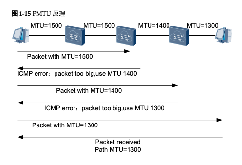
The whole transmission path needs to pass through four links, and the MTU of each link is 1500, 1500, 1400 and 1300 respectively. When the source node sends a slice message, it first slices and sends the slice message according to the PMTU of 1500, and when it reaches the outgoing interface with MTU of 1400, the device returns Packet Too Big error and carries the MTU value of 1400. When the source node receives the message, it reslices the message according to the PMTU of 1400 and sends a slice message again. After that, the source node slices the message again according to the PMTU of 1300 and sends a slice message to the destination, so that the PMTU of the path is found.
Linux IPv6
| items | ipv4 | ipv6 |
|---|---|---|
| sysctl configuration items | net.ipv4.conf | net.ipv6.conf |
| ip address | When you look through the ip a, you can see the inet followed by the ipv4 address. | When you look through ip a, you can see that the address after inet6 is the ipv6 address. There are usually more than one, scope global is the global unique unicast address or unique local address (starting with fc or fd) and scope link is the link local address (starting with fe80). |
| dump | tcpdump icmp/ tcpdump ip | tcpdump icmp6 / tcpdump ip6 |
| ping | ping | ping6 or ping -6 |
| traceroute6 | traceroute | traceroute6 |
| Neighborhood Address Resolution | arping | ndisc |
| Routing Table | ip r | ip -6 r |
| Neighborhood Address Table | ip neigh 或 arp -n | ip -6 neigh |
| DNS resolution | dig | dig -6 |
IPv4/IPv6 Dual Stack for Kubernetes
IPv4/IPv6 dual-stack is a solution for the transition from IPv4 to IPv6, where a network interface has both IPv4 and IPv6 addresses, so that when communicating with a remote end, it can use IPv6 if the remote end supports IPv6, but otherwise it can also use IPv4. Kubernetes started supporting dual stacks after 1.20. Of course, in addition to the Kubernetes version requirements, the CNI plug-in must also support dual-stacking.
To enable dual stack in Kubernetes, the following configuration is required.
- kube-apiserver:
--service-cluster-ip-range=<IPv4 CIDR>,<IPv6 CIDR>
- kube-controller-manager:
--cluster-cidr=<IPv4 CIDR>,<IPv6 CIDR>--service-cluster-ip-range=<IPv4 CIDR>,<IPv6 CIDR>--node-cidr-mask-size-ipv4|--node-cidr-mask-size-ipv6Defaults to /24 for IPv4 and /64 for IPv6
- kube-proxy:
--cluster-cidr=<IPv4 CIDR>,<IPv6 CIDR>
IPv6 Address Quick Search
You usually have more contact with IPv4 addresses, so you can probably know what a certain address means at a glance, but it is often difficult to distinguish in IPv6, so here is a table for reference.
| Type | IPv4 | IPv6 |
|---|---|---|
| Loopback Address | 127.0.0.1 | ::1/128 |
| Private Network Address | 10.0.0.0 - 10.255.255.255, 172.16.0.0 - 172.31.255.255,192.168.0.0 - 192.168.255.255 | Prefix FC00::/7(1111 110),Scope:FC~FD。 |
| Link Local Address | 169.254.0.0/16 | fe80::/10 |
| Multicast address | None | The multicast address of the requested node consists of the prefix FF02::1:FF00:0/104 and the last 24 bits of the unicast address. |
| Broadcast Address | The broadcast address uses the largest address in the range of the network. That is, an address where all bits of the host portion are 1. In network 10.1.1.0/24, the broadcast address is 10.1.1.255. | None |