The first time I got to know VXLAN was when I looked at a network plugin called flannel used in k8s that has a VXLAN mode, which implements an Overlay Network that connects all containers together. So in this article, let’s take a look at how VXLAN connects the networks between different containers.
Overview
Before we look at VXLAN, let’s take a look at its predecessor, VLAN, whose full name is Virtual Local Area Network, a layer 2 (data link layer) network used to partition broadcast domains. Because with more computers, if there is only one broadcast domain, there will be a lot of broadcast frames (e.g. ARP requests, DHCP, RIP all generate broadcast frames) forwarded to all clients in the same network.
This results in unnecessary waste. On the one hand, the broadcast message consumes the overall bandwidth of the network, and on the other hand, the computer receiving the broadcast message consumes some CPU time to process it. This results in a significant and unnecessary consumption of network bandwidth and CPU computing power.
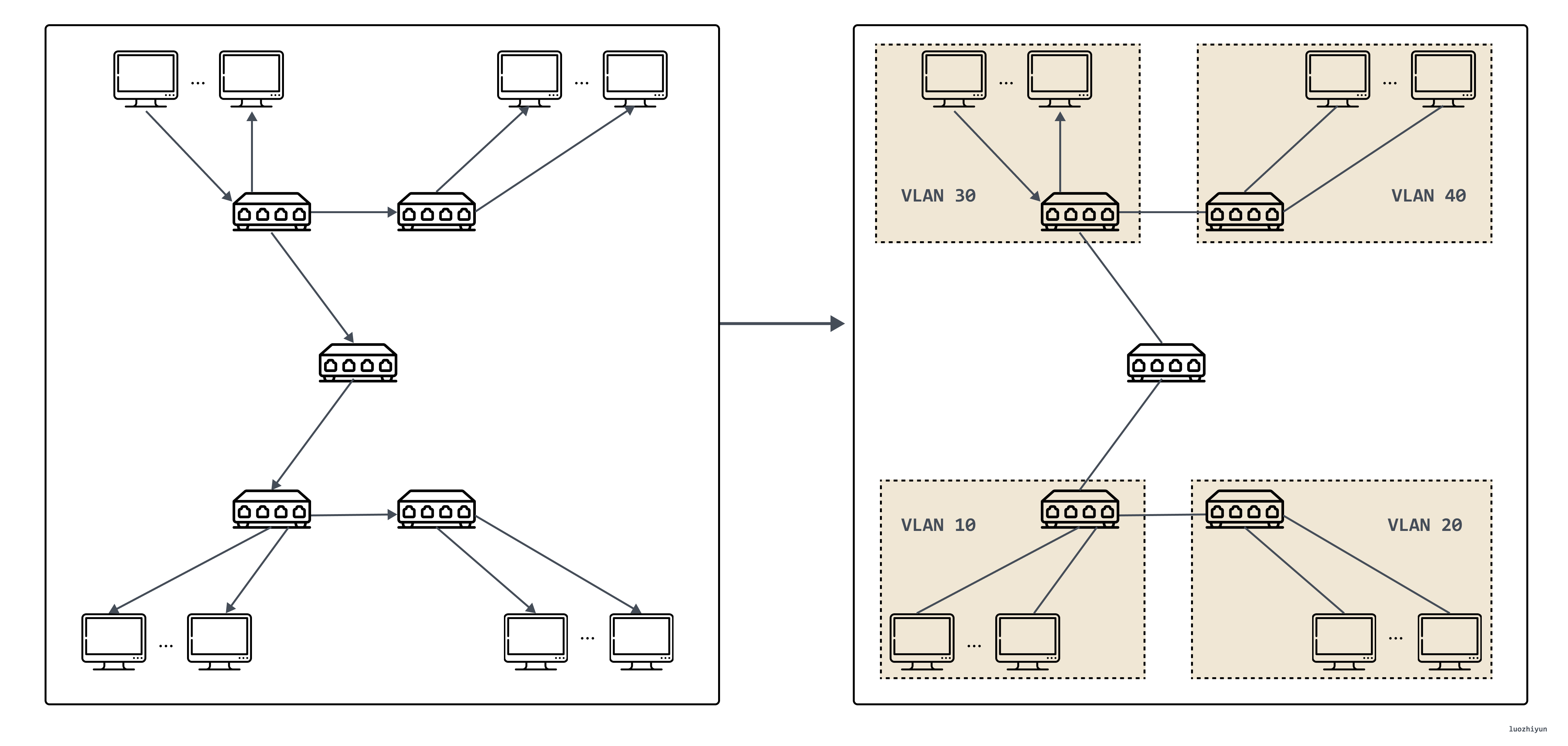
In this case, VLAN technology emerged. This technology can divide a LAN into multiple logical VLANs, each VLAN is a broadcast domain, and the communication between hosts within a VLAN is the same as within a LAN, while inter-VLANs cannot interoperate directly, and broadcast messages are restricted to a VLAN. As shown in the figure below.
However, VLANs have two obvious flaws, the first one is the design of VLAN Tag, the 802.1Q specification that defines VLANs was proposed in 1998, and only 32 Bits of storage space is reserved for VLAN Tag, of which only 12 Bits can be used to store VLAN IDs. When the cloud computing data center emerges, even without considering the demand of virtualization, the physical devices that need to assign IPs alone may be tens of thousands or even hundreds of thousands, so 4096 VLANs are definitely not enough.
The second drawback of VLAN is that it is itself a Layer 2 network technology. However, information between two independent data centers can only be passed through the Layer 3 network. The development of cloud computing has popularized the demand of many businesses to operate across data centers, so passing VLAN tags between data centers is another troublesome task; and in the virtual network, a physical machine will have multiple containers, and the number of containers and VMs is also increasing by orders of magnitude, and each VM has its own IP address and MAC address, so the pressure on the switch is also multiplied.
For all the above reasons, VXLAN also comes into play.
VXLAN Protocol
Protocol messages
VXLAN (Virtual eXtensible LAN) uses the L2 over L4 (MAC in UDP) packet encapsulation mode, which puts the Ethernet frames originally transmitted at Layer 2 into the packet body of Layer 4 UDP protocol, and adds its own defined VXLAN Header.
The VXLAN Header directly contains 24 Bits of VLAN IDs, which can also store 16.77 million different values. VXLAN allows Layer 2 networks to scale within Layer 3 and is no longer limited by the transmission between data centers.
VXLAN works on Layer 2 networks (IP network layer) and can be deployed on any network that is Layer 3 reachable (capable of communicating with each other over IP.) The entire message structure of VXLAN is shown in Figure.
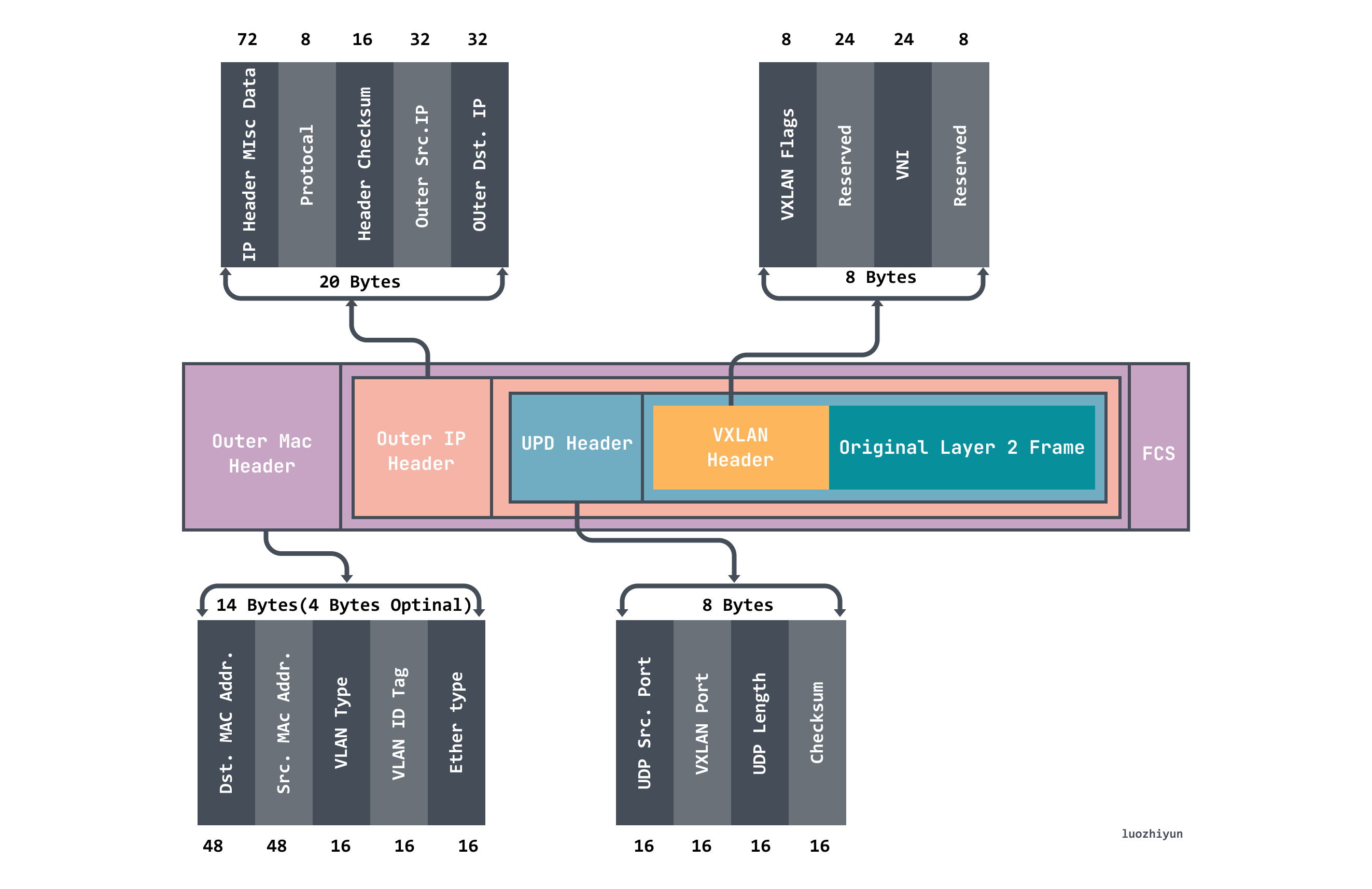
Above we can see that the VXLAN message wraps the Original Layer2 Frame.
- VXLAN Header 8 bytes, which contains the 24Byte VNI field used to define the different tenants in the VXLAN network and can store 16.77 million different fetch values.
- UDP Header, where the VXLAN header is used as data for the UDP along with the original Ethernet frame, the destination port number (VXLAN Port) in the header is fixed at 4789 and the source port is randomly assigned by flow (hash operation by MAC, IP, Layer 4 port number), which allows better ECMP.
- Outer IP Header encapsulates the outer IP header, encapsulating the destination IP address and source IP address, where IP refers to the IP address of the host.
- Outer MAC Header encapsulates the outer Ether header, encapsulating the source MAC address, the destination MAC address, where MAC address refers to the host MAC address.
Working model
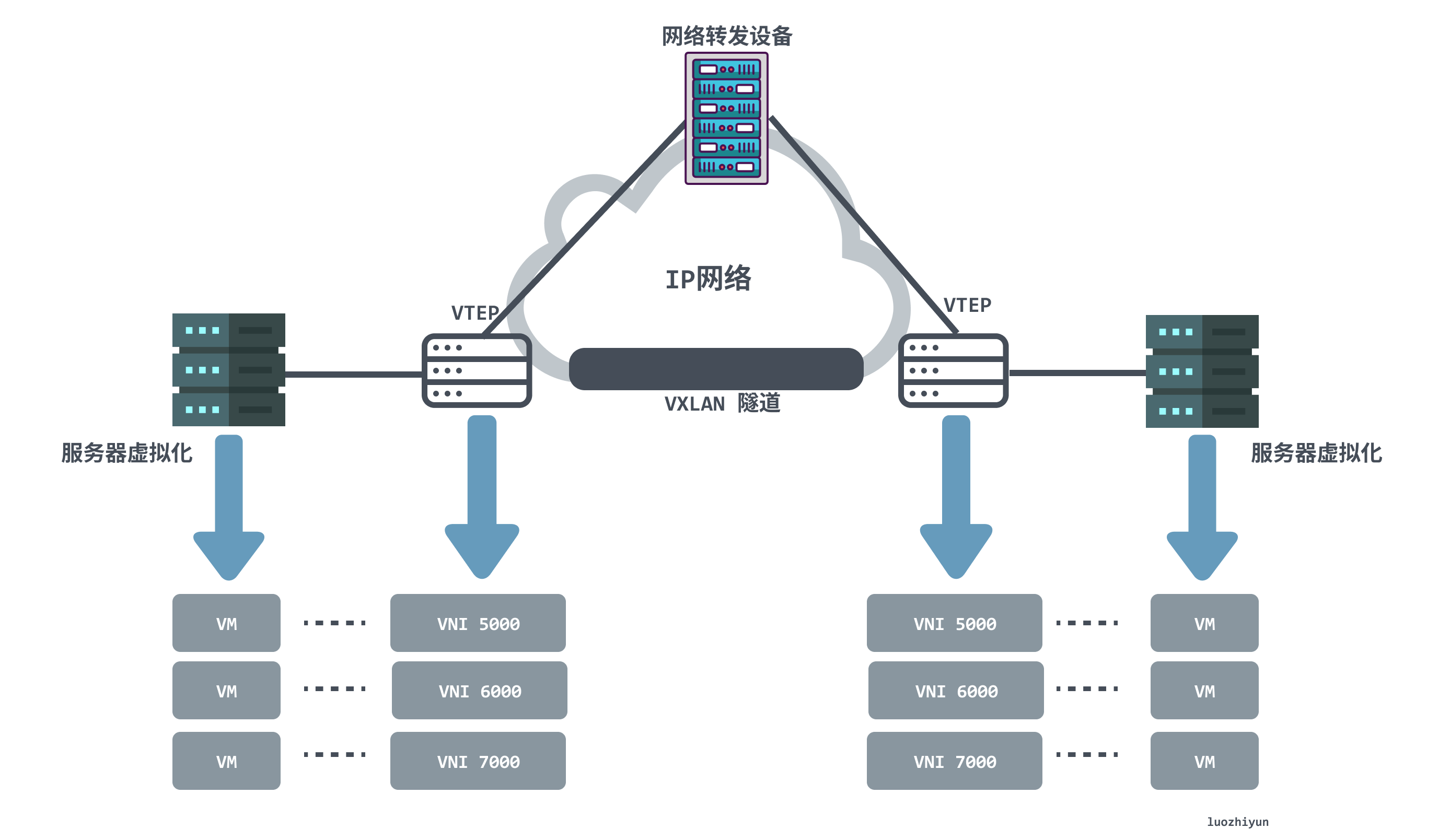
From the above diagram VXLAN network network model we can find the following components appearing in the VXLAN network.
- VTEP (VXLAN Tunnel Endpoints): An edge device of a VXLAN network that is the starting and ending point of a VXLAN tunnel and is responsible for the encapsulation and unencapsulation of VXLAN protocol messages, i.e., encapsulating the message headers of VTEP traffic on virtual messages. VTEP can be a network device (e.g., a switch) or a machine (e.g., a host in a virtualized cluster).
- VNI (VXLAN Network Identifier): As mentioned earlier, VLANs only take up 12 bits of space in Ethernet data frames, which makes the isolation capability of VLANs overwhelming in data center networks. The emergence of VNI is specifically to solve this problem. Generally each VNI corresponds to one tenant and it is a 24-bit integer, meaning that a public cloud built using VXLAN can theoretically support up to 16.77 million levels of tenants.
- VXLAN tunneling: Tunneling is a logical concept that has no specific physical entity trying to correspond in the VXLAN model. A tunnel can be thought of as a virtual channel where both sides of the VXLAN communication (the VMs in the diagram) think they are communicating directly and are unaware of the existence of the underlying network. As a whole, each VXLAN network looks like a separate communication channel, or tunnel, for the communicating VMs.
Communication process
Usually VTEPs in VXLAN networks may have multiple tunnels. VTEPs determine the destination VTEP address before communicating by querying the forwarding table FDB, which is used to store the MAC address of the remote VM/container, the remote VTEP IP, and the VNI mapping relationship, and the forwarding table is constructed by flooding and learning mechanisms. Traffic whose destination MAC address does not exist in the forwarding table is called Unknown unicast. the VXLAN specification requires flooding using IP multicast to send packets to all VTEPs except the source VTEP. when the destination VTEP sends back response packets, the source VTEP learns the mapping relationships of MAC address, VNI, and VTEP from them and adds to the forwarding table.
Let’s take a look at the first communication process to see how VTEP learns.
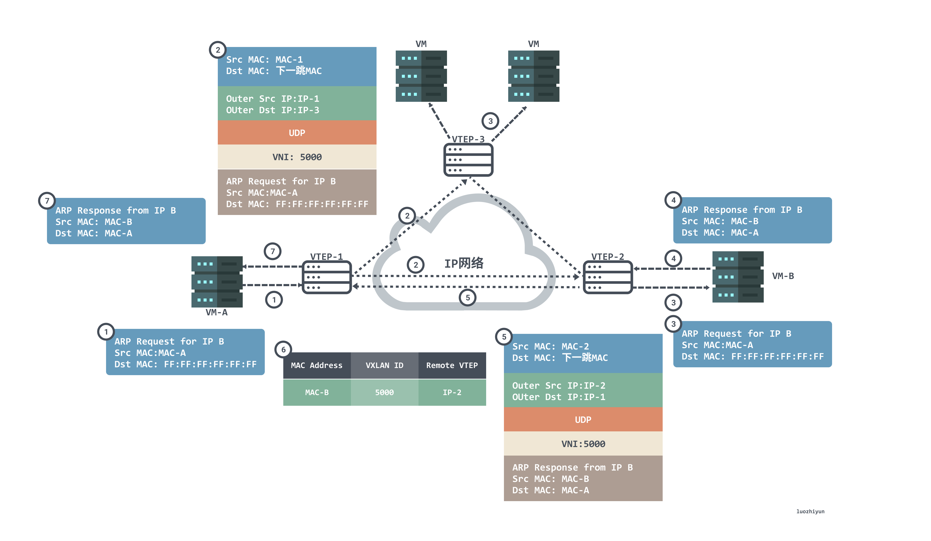
- Since this is the first time we are communicating, VM-A does not have the MAC address of VM-B on it. VM-A sends an ARP broadcast message requesting the MAC address of VM-B. VM-A sends an ARP broadcast message with source MAC of VM-B, destination MAC of full F, source IP of IP-A, and destination IP of IP-B to request the MAC address of VM-B.
- After VTEP-1 receives an ARP request, it determines that the message needs to enter the VXLAN tunnel according to the configuration on the Layer 2 sub-interface. VTEP-1 will encapsulate the message, and the outer source IP address of the encapsulation is the IP address of the local VTEP (VTEP-1). The outer destination IP address is the IP address of the peer VTEP (VTEP-2 and VTEP-3); the outer source MAC address is the MAC address of the local VTEP, and the outer destination MAC address is the MAC address of the next-hop device in the network going to the destination IP.
- After the message arrives at VTEP-2 and VTEP-3, VTEP decapsulates the message to obtain the original message sent by VM-A. Then VTEP-2 and VTEP-3 process the message accordingly and broadcast it in the corresponding Layer 2 domain. VM-B and VM-C receive the ARP request and compare whether the destination IP address in the message is the local IP address. VM-C discards the message if it finds that the destination IP is not the local IP. The VM-B finds that the destination IP is the local IP, and then responds to the ARP request.
- The VM-B will answer the ARP packet based on the requested ARP packet as a unicast message with MAC-B as the source MAC and MAC-A as the destination MAC, IP-B as the source IP and IP-A as the destination IP.
- After receiving the ARP reply message from VM-B, VTEP-2 identifies the VNI to which the message belongs, and VTEP-2 encapsulates the message. The outer source IP address of the encapsulation is the IP address of the local VTEP (VTEP-2), and the outer destination IP address is the IP address of the counterpart VTEP (VTEP-1); the outer source MAC address is the MAC address of the local VTEP, and the outer destination MAC address is the MAC address of the next-hop device in the network going to the destination IP.
- After the message arrives at VTEP-1, VTEP-1 decapsulates the message to get the original message sent by VM_B. At the same time, VTEP-1 learns the correspondence between the MAC address of VM_B, VNI and the IP address (IP-2) of the remote VTEP, and records it in the local MAC table. Afterwards, VTEP-1 sends the decapsulated message to VM-A.
- At this point, VM-A has received the MAC address of VM-B in response to the ARP broadcast message.
In addition to the above multicast learning method to obtain MAC <--> VNI <--> VTEP IP this set of mapping relations there is another way, is a distributed control center.
For example, the MAC addresses of VTEPs in a Flannel’s VXLAN mode network are not learned through multicast, but are synchronized (or etcd) through the apiserver. When each node creates a Flannel, each node will report its VTEP information to apiserver, and apiserver will then synchronize to the listener (Flanneld) who is watching the node api on each node, and after Flanneld gets the update message, it will send it down to the Flanneld gets the update message and then sends it down to the kernel via netlink to update the FDB (query forwarding table) table entries, thus synchronizing the whole cluster. This apiserver plays the role of a distributed control center, and no longer needs to send extra requests to the full network to get the corresponding mapping information.
An example
Here, we make a VXLAN network by ourselves, and then analyze its packets, whether it is consistent with the conclusions we have told at length above. Note that when experimenting on your own virtual machine, to avoid unnecessary trouble, remember to turn off the firewall, centos command is: systemctl stop firewalld.
Here we are going to experiment with docker, the idea is to create a VXLAN interface on each of the two container hosts and connect the VXLAN interface to the port of the docker bridge as follows.
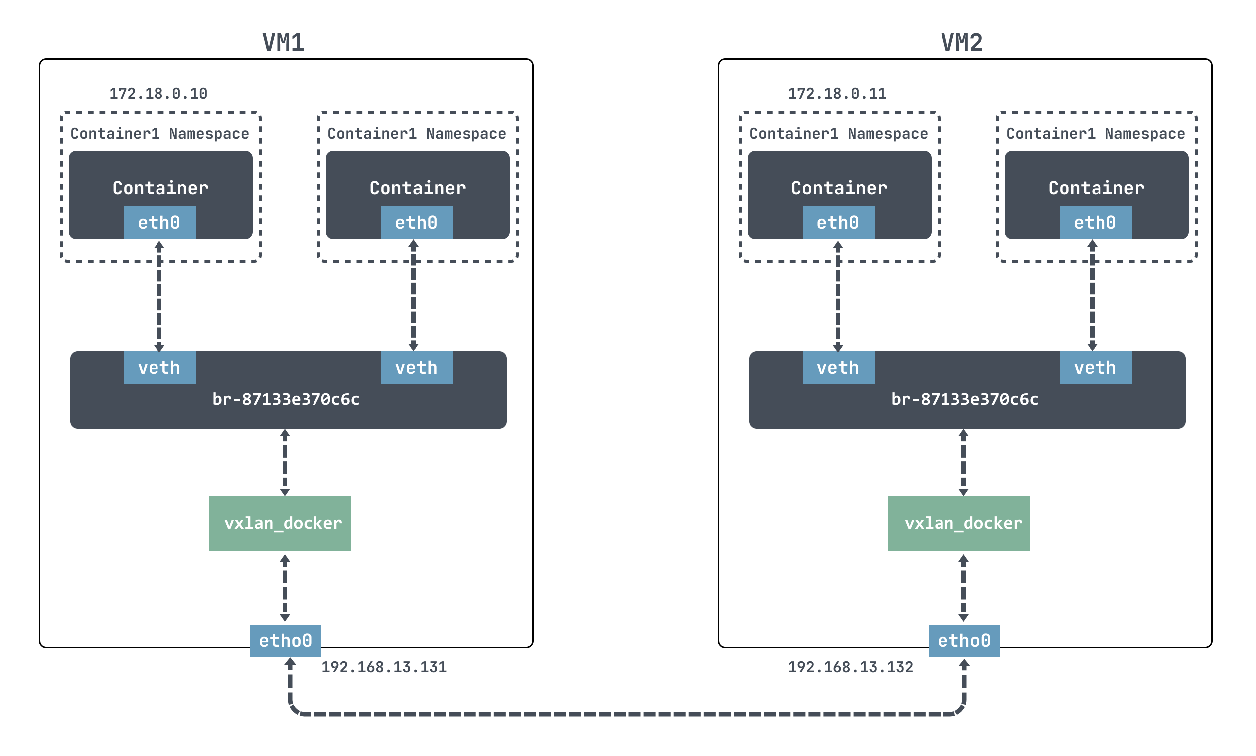
For docker, it is not possible to communicate directly across nodes, so we use VXLAN here to simulate cross-node communication.
By default, docker uses the 172.17.0.0/16 network segment, and the IP addresses of docker containers are assigned starting from 172.17.0.2. In order to take advantage of the -ip parameter for custom IP addresses, you need to create a custom network first, specifying the network segment 172.18.0.0/16.
|
|
We can also see that docker has created a new bridge for our new network.
Create a new container as follows.
Above we have created the network, but we can’t communicate by going in directly.
|
|
Here we create a VXLAN interface on each of the two container hosts and connect the VXLAN interface to the port of the docker bridge.
|
|
Above we used ip link add to create a VXLAN network interface with VNI 200 for VM1 and VM2 respectively, with the name vxlan_docker; then we used brctl addif to connect the newly created VXLAN interface vxlan_docker to the docker bridge.
Then we go into the container and find that we can ping through.
|
|
Analyze packets on the host.
|
|
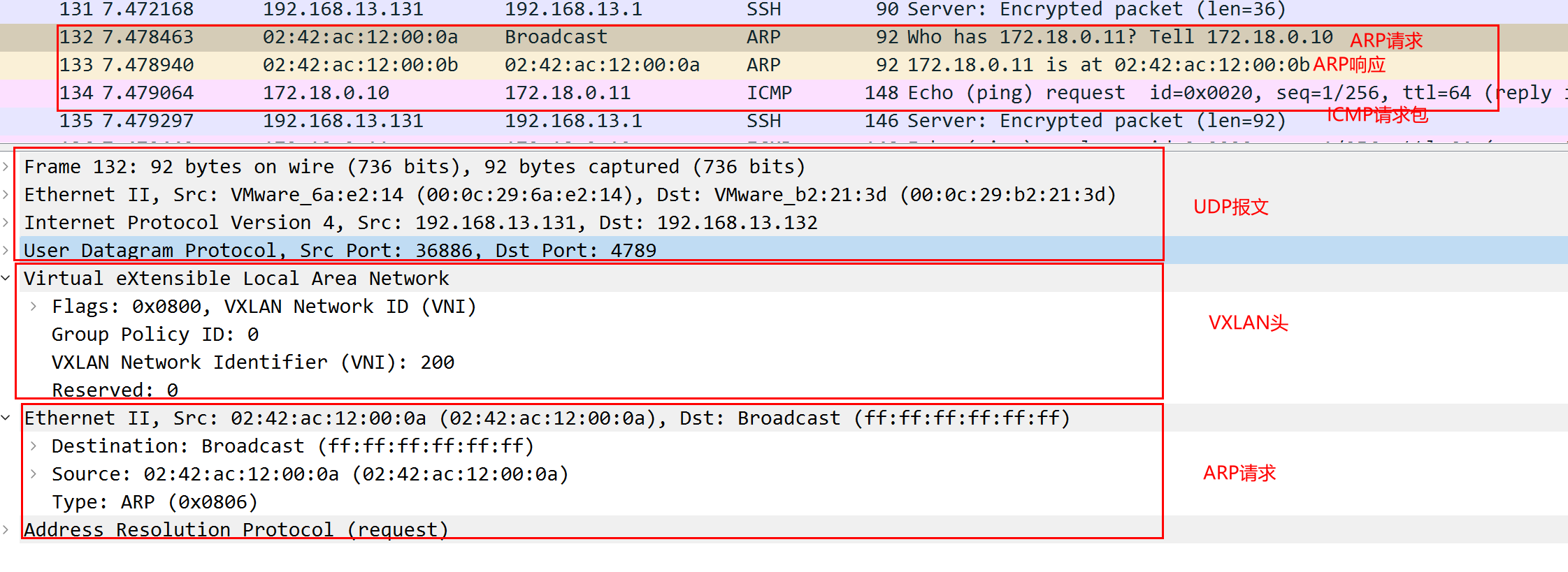
Above we see that the first is to send out an ARP request for a MAC address, the outer layer is a UDP message, the destination port is 4789, the destination IP is the IP of the host VM2; the VXLAN message header VNI is 200; the source MAC address of the ARP request is the MAC address of the container sending the message inside VM1, the destination address is not obtained, it is ff:ff:ff:ff: ff:ff.
After receiving the return packet, 172.18.0.11 replies with an ARP response packet informing that the MAC address is 02:42:ac:12:00:0b, and then it can send ICMP packets normally.
Summary
This article, starting from the introduction of VLAN, tells what are the disadvantages of VLAN and why there is VXLAN, then tells how the protocol messages of VXLAN are encapsulated, how the overall working model is, and how the VXLAN communication process is familiar with how it works, and finally, through an example of hands-on implementation of mutual communication between containers on two nodes. I believe that by this point, you should have a lot of understanding of VXLAN.