LVS is the abbreviation of Linux Virtual Server, which means Linux Virtual Server, a virtual server clustering system. LVS is a free software project initiated by Dr. Wen-Song Zhang, and is mainly used for load balancing of multiple servers. It works at the network layer and can achieve high performance, high availability server clustering technology.
- It is cheap and can combine many low performance servers together to form a super server.
- It is easy to use, very simple to configure, and has multiple methods of load balancing.
- It is stable and reliable, even if one of the servers in the cluster is not working properly, it does not affect the overall effect.
- Scalability is also very good.
LVS is a load balancer that works at layer 4. Its implementation is similar to iptables/netfilter, working on the TCP/IP stack in kernel space. LVS works on the INPUT Hook Funtion and sets additional rules at INPUT. Once a client requests a clustered service, LVS will forcefully modify the request message and send it to POSTROUTING to be forwarded to the back-end host.
Similar to iptables/netfilter, LVS is also two-part.
- ipvsadm: works in user space and is responsible for defining and managing rules for clustered services
- ipvs: works in the kernel, and prior to 4.23, the kernel had to be patched to and recompiled. In versions after 2.4.23 and 2.6, ipvs is built directly into the kernel.
Device address naming for LVS clusters
- VIP: Virtual IP, the IP address of the LVS for user requests
- RIP: Real server IP, the IP address used by the back-end server to communicate with the LVS
- DIP: Director IP, the IP address used by LVS users to communicate with the back-end server
- CIP: Client IP, the client IP address
Features of LVS.
- High availability: LVS is a kernel-level based application software, so it has high processing performance. The load balancing cluster system framed with LVS has excellent processing capability, and the failure of each service node will not affect the normal use of the whole system, while achieving reasonable load balancing, so that the application has super high load service capability and can support millions of concurrent connection requests. If configured with a 100Gb/s NIC, the throughput of the whole cluster system can be as high as 1Gbits/s with VS/TUN or VS/DR scheduling technology; if configured with a Gigabit NIC, the maximum throughput of the system can be close to 10Gbits/s.
- High reliability: LVS load balancing cluster software has been well popularized and used in enterprises, schools and other industries, and many large and critical web sites at home and abroad have adopted LVS cluster software, so its reliability has been well proven in practice. There are many load balancing systems made with LVS that have been running for a long time and have never been restarted. All these show the high stability and reliability of LVS.
- LVS only supports Linux and FreeBSD systems for the front-end Director Server, but it supports most TCP and UDP protocols. LVS has no restrictions on the operating system of Real Server, which can run on any operating system that supports TCP/IP, including Linux, various Unix (such as FreeBSD, Sun Solaris, HP Unix, etc.), Mac/OS and Windows, etc.
- Open source software: LVS cluster software is free software distributed under GPL (GNU Public License) license, so users can get the source code of the software and can make various modifications according to their needs, but the modifications must be distributed under GPL.
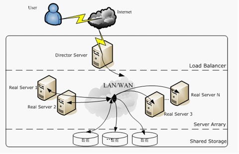
LVS structural system
A server cluster system built with LVS has three components: the front-end load balancing layer, represented by Load Balancer, the middle server cluster layer, represented by Server Array, and the bottom data sharing storage layer, represented by Shared Storage, where all internal applications appear transparent to the user, who is simply using a high-performance service provided by a virtual server.
-
Load Balancer Layer : This is the core part of LVS, it is like the Controller of the MVC model of the website. It is responsible for distributing customer requests to different servers in the next layer for processing according to a certain algorithm, and does not do specific business processing itself. The LVS module is installed on the Director Server, whose main role is similar to that of a router, containing the routing tables set up to accomplish the LVS function, and distributing user requests to the application servers (Real Server) on the Server Array layer. At the same time, the Director Server should also be installed on the Real Server service monitoring module Ldirectord, this module is used to monitor the health of each Real Server service. The Real Server is removed from the LVS routing table when it is unavailable and rejoined when it is restored.
-
Server Array Layer : This layer is responsible for specific services. It consists of a group of machines that actually run application services. Real Server can be one or more of WEB server, MAIL server, FTP server, DNS server, video server, and each Real Server is connected to each other through a high-speed LAN or a WAN distributed all over the world. In actual application, Director Server can also play the role of Real Server at the same time.
-
Shared Storage layer : is to provide shared storage space and content consistency for all Real Server storage area, in physical, generally have a disk array device composition, in order to provide content consistency, generally can share data through the NFS network file system, but NFS in a busy business system, the performance is not very good, at this time can use a cluster file system, such as Red hat’s GFS file system, oracle provides OCFS2 file system, etc.
Operating modes of LVS
There are many implementations of load balancing technology, there are methods based on DNS domain name rotation resolution, methods based on client-side scheduling access, methods based on application layer system load scheduling, and methods based on IP address scheduling, among these load scheduling algorithms, the most efficient execution is IP load balancing technology.
The IP load balancing technology of LVS is implemented through the IPVS module, which is the core software of the LVS cluster system, and its main role is that it is installed on the Director Server, while an IP address is virtualized on the Director Server, and users must access the service through this virtual IP address. This virtual IP is generally called the VIP of LVS, i.e. Virtual IP, and the request for access first reaches the load scheduler through the VIP, which then selects a service node from the Real Server list to respond to the user’s request. When the user’s request arrives at the load scheduler, how the scheduler sends the request to the Real Server node that provides the service, and how the Real Server node returns data to the user is the key technology implemented by IPVS. There are three load balancing mechanisms implemented by IPVS, namely NAT, TUN and DR, as detailed below.
VS/NAT(Virtual Server via Network Address Translation)
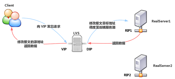
LVS-NAT model is similar to DNAT, and the working mechanism is the same as DNAT. When a client requests a cluster service, LVS modifies the destination address of the request message to RIP, forwards it to the back-end RealServer, and modifies the source address of the back-end response message to VIP, and responds to the client.
Under the LVS-NAT model, the Director’s incoming and outgoing request messages pass through the Director, so the pressure on the Director is relatively high.
Features of LVS-NAT.
- Cluster nodes and Director must be in the same IP network.
- RIP is usually a private address and is only used for communication between cluster nodes.
- The Director is located between the client and the Realserver and is responsible for handling all incoming and outgoing messages.
- Realserver must point the gateway to DIP
- Port mapping is supported
- Director can be a bottleneck in larger scale application scenarios
Even if it is the load balancer that becomes the bottleneck of the whole system, if so there are two ways to solve it. One is a hybrid approach and the other is to use Virtual Server via IP tunneling or Virtual Server via direct routing. if you use the hybrid approach, you will need many RR DNS domains that belong to the same single RR. You use Virtual Server via IP tunneling or Virtual Server via direct routing for better scalability. You can also nest load balancers, with VS-Tunneling or VS-Drouting at the top, and then VS-NAT at the back.
VS/TUN(Virtual Server via IP Tunneling)
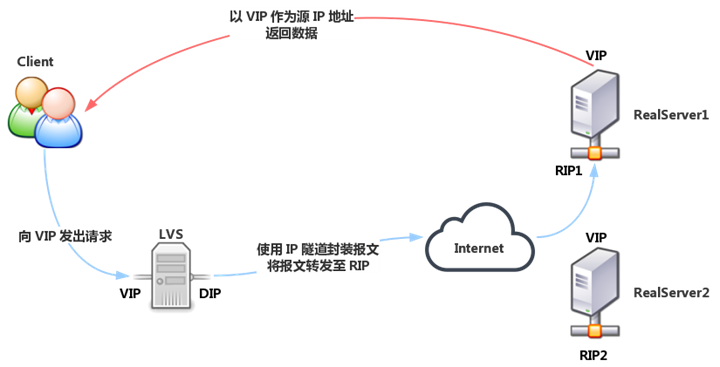
Similar to the DR model, the Realserver is equipped with an invisible VIP, and the RIP of the Realserver is a public address, and may not be in the same network as the DIP. When the request reaches Director, Director does not modify the source IP and destination IP address of the request message, but uses IP tunneling technology, using DIP as the source IP and RIP as the destination IP to encapsulate the request message again and forward it to the Realserver of RIP, which still uses VIP as the source address after parsing the message. After parsing the message, the Realserver still uses VIP as the source address to respond to the client.
Features of LVS-TUN.
- Cluster nodes and can span the Internet
- RIP, DIP, and VIP are all public network addresses
- The Director only handles inbound requests, and the response messages are sent directly from the Realserver to the client.
- Realserver uses its own gateway instead of Director
- Realserver can only use operating systems that support tunneling
- Port mapping is not supported
VS/DR(Virtual Server via Direct Routing)
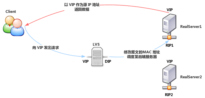
DR value Direct Routing, direct routing, DR model, Director and Realserver in the same network, for Director, VIP for receiving client requests, DIP for communication with Realserver. For Realserver, each Realserver is equipped with the same VIP as Director (this VIP is hidden, turning off the response to ARP requests), only users respond to client requests, and RIP is used to communicate with Director.
When a client requests a cluster service, the request message is sent to Director’s VIP (Realserver’s VIP does not respond to ARP requests), and Director re-encapsulates the source and destination MAC addresses of the client message, forwards the message to Realserver, and Realserver receives the forwarded message. At this time, the source IP and destination IP of the message are not modified, so the Realserver receives the request message with the destination IP address of the locally configured VIP, and it will use its own VIP to respond directly to the client.
LVS-DR model, the client’s response message will not go through the Director, so the Director’s concurrency capacity is greatly improved.
Features of the LVS-DR model.
- Ensure that the front-end router will send the message whose destination address is VIP to Director through ARP parsing.
- static binding: in the front-end routing VIP corresponding to the target MAC address is statically configured to the MAC address of the Director VIP interface.
- arptables: in each Realserver, through the arptables rule to deny its response to the VIP ARP broadcast request
- modify the kernel parameters: modify the kernel parameters on the Realserver, and combined with the configuration of the address to achieve the refusal to respond to the VIP ARP broadcast requests
- Each RIP must be in the same physical network with DIP
- RS RIPs can use private addresses or public addresses to facilitate configuration
- Director is only responsible for processing inbound requests, and response messages are sent directly from Realserver to the client
- Realserver cannot point the gateway to DIP, but use the front-end gateway directly
- Port mapping is not supported
LVS-FULLNAT
FULLNAT is developed by Taobao, it has not been added to the kernel available for CentOS yet, and it needs to be patched to the kernel when using it.
Similar to DNAT, it modifies the source address of the request message to DIP and the destination address to RIP to achieve forwarding. For the response message, the source address is modified to VIP and the destination address is modified to CIP to achieve forwarding.
Features.
- RIP, DIP can use private address
- RIP and DIP can no longer be in the same network, and the gateway of RIP does not need to point to DIP
- Port mapping support
- Both request and response packets are routed through Director
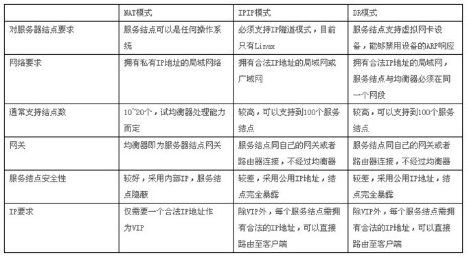
Specific comparison.
Scheduling algorithm for LVS
For different network service requirements and server configurations, the IPVS scheduler implements the following eight load scheduling algorithms.
- Round Robin: “Polling” scheduling, also known as 1:1 scheduling, allows the scheduler to assign external user requests to each Real Server in the cluster in a sequential 1:1 manner through a “polling” scheduling algorithm. This algorithm treats each Real Server equally, regardless of the actual load and connection status on the server.
- Weighted Round Robin: The “weighted round robin” scheduling algorithm schedules access requests based on the different processing capabilities of Real Servers. Different scheduling weights can be set for each Real Server. For Real Servers with relatively good performance, higher weights can be set, while for Real Servers with weaker processing power, lower weights can be set, thus ensuring that servers with strong processing power handle more access traffic. The server resources are fully and reasonably utilized. At the same time, the scheduler can also automatically query the load of Real Server and dynamically adjust its weight value.
- Least Connections: The “Least Connections” scheduling algorithm dynamically schedules network requests to the server with the lowest number of established links. If the real servers in a cluster system have similar system performance, the “Least Connections” scheduling algorithm can be used to better balance the load.
- Weighted Least Connections: “Weighted Least Connections Scheduling” is a superset of “Least Connections Scheduling”, where each service node can express its processing capacity with a corresponding weight value. The default value is 1. Weighted Least Connections Scheduling allocates new connection requests in such a way that the number of established connections to a service node is as proportional as possible to its weight value.
- Locality-Based Least Connections: The “Locality-Based Least Connections” scheduling algorithm is a load balancing algorithm for the target IP address and is currently used in Cache clustering systems. If the server is available and not overloaded, the request is sent to that server; if the server does not exist, or if the server is overloaded and there is a server at half workload, an available server is selected using the “least link” principle and the request is sent to that server. If the server does not exist, or if the server is overloaded and there is a server at half workload, a server is selected as available using the “least link” principle and the request is sent to that server.
- Locality-Based Least Connections with Replication: The “Locality-Based Least Connections with Replication” scheduling algorithm is also a load balancing algorithm for target IP addresses and is currently used mainly in Cache clustering systems. It is currently used in Cache clustering systems. It differs from the LBLC algorithm in that it maintains a mapping from a target IP address to a set of servers, while the LBLC algorithm maintains a mapping from a target IP address to a single server. The algorithm finds the server group corresponding to the target IP address of the request, selects a server from the server group according to the “least connected” principle, and sends the request to that server if the server is not overloaded, and if the server is overloaded; then selects a server from the cluster according to the “least connected” principle. If the server is overloaded, then a server is selected from this cluster on the “minimum connection” principle, added to the server group, and the request is sent to that server. Also, when the server group has not been modified for a period of time, the busiest server is removed from the server group to reduce the level of replication.
- Destination Hashing: The “destination hashing” scheduling algorithm finds the corresponding server from the statically assigned hash table based on the requested destination IP address as a hash key. If the server is available and not overloaded, the request is sent to that server, otherwise it returns null.
- Source Hashing: The “Source Hashing” scheduling algorithm uses the requested source IP address as the Hash Key to find the corresponding server from the statically assigned hash table. Otherwise, it returns null.