Note: Any network configuration created or modified with the ip command in this article is not persistent and disappears upon host reboot.
Linux has powerful virtual networking capabilities, which are the basis for virtual networks such as openstack networks, docker container networks, and kubernetes networks.
Here are the most common types of virtual network interfaces for Linux: TUN/TAP, bridge, veth, ipvlan/macvlan, vlan, and vxlan/geneve.
I. tun/tap Virtual Network Interface
tun/tap are virtual network devices in the OS kernel, they provide data reception and transmission for user layer programs.
A normal physical network interface, such as eth0, has a kernel stack and an external physical network on each side.
For a TUN/TAP virtual interface such as tun0, one end must be connected to the user layer program, while the other end varies depending on how it is configured, either directly to the kernel stack or to a bridge (described later). Linux provides tun/tap functionality through the kernel module TUN, which provides a device interface /dev/net/tun for user-level programs to read and write data from the host kernel stack through /dev/net/tun.
 1
 2
 3
 4
 5
 6
 7
 8
 9
10
11
|
> modinfo tun
filename:       /lib/modules/5.13.6-1-default/kernel/drivers/net/tun.ko.xz
alias:          devname:net/tun
alias:          char-major-10-200
license:        GPL
author:         (C) 1999-2004 Max Krasnyansky <maxk@qualcomm.com>
description:    Universal TUN/TAP device driver
...

> ls /dev/net/tun
/dev/net/tun
|
An example diagram of a TUN device is as follows.
 1
 2
 3
 4
 5
 6
 7
 8
 9
10
11
12
13
14
15
16
17
18
19
20
21
22
23
24
25
26
27
28
29
30
|
+----------------------------------------------------------------------+
|                                                                      |
|  +--------------------+      +--------------------+                  |
|  | User Application A |      | User Application B +<-----+           |
|  +------------+-------+      +-------+------------+      |           |
|               | 1                    | 5                 |           |
|...............+......................+...................|...........|
|               ↓                      ↓                   |           |
|         +----------+           +----------+              |           |
|         | socket A |           | socket B |              |           |
|         +-------+--+           +--+-------+              |           |
|                 | 2               | 6                    |           |
|.................+.................+......................|...........|
|                 ↓                 ↓                      |           |
|             +------------------------+          +--------+-------+   |
|             | Network Protocol Stack |          |  /dev/net/tun  |   |
|             +--+-------------------+-+          +--------+-------+   |
|                | 7                 | 3                   ^           |
|................+...................+.....................|...........|
|                ↓                   ↓                     |           |
|        +----------------+    +----------------+        4 |           |
|        |      eth0      |    |      tun0      |          |           |
|        +-------+--------+    +-----+----------+          |           |
|    10.32.0.11  |                   |   192.168.3.11      |           |
|                | 8                 +---------------------+           |
|                |                                                     |
+----------------+-----------------------------------------------------+
                 ↓
         Physical Network
|
Since one end of the TUN/TAP device is the kernel stack, obviously the packets flowing into tun0 are first matched by local routing rules.
After the routing match is successful and the packet is sent to tun0, tun0 discovers that the other end is connected to application B via /dev/net/tun and drops the data to application B.
After the application processes the packet, it may construct a new packet and send it out through the physical NIC. For example, a common VPN program encapsulates/encrypts the original packet and sends it to the VPN server.
C programming to test the TUN device
In order to use the tun/tap device, the user application needs to open /dev/net/tun with a system call to get a file descriptor (FD) to read/write the device and call ioctl() to register a virtual NIC of type TUN or TAP with the kernel (instantiating a tun/tap device), which may be named tun0/tap0, etc. After that, the user application can use the device to read/write the device.
Thereafter, the user program can interact with the host kernel stack (or other network devices) through this TUN/TAP virtual NIC. When the user-level program is closed, its registered TUN/TAP virtual NIC and the automatically generated routing table-related entries are released by the kernel.
The user layer program can be thought of as another host on the network that is connected via the tun/tap virtual NIC.
An example of a simple C program that simply prints the number of bytes received each time it receives data is as follows.
 1
 2
 3
 4
 5
 6
 7
 8
 9
10
11
12
13
14
15
16
17
18
19
20
21
22
23
24
25
26
27
28
29
30
31
32
33
34
35
36
37
38
39
40
41
42
43
44
45
46
47
48
49
50
51
52
53
54
55
56
57
58
59
60
61
62
63
64
65
66
67
68
|
#include <linux/if.h>
#include <linux/if_tun.h>

#include <sys/ioctl.h>

#include <fcntl.h>
#include <string.h>

#include <unistd.h>
#include<stdlib.h>
#include<stdio.h>

int tun_alloc(int flags)
{

    struct ifreq ifr;
    int fd, err;
    char *clonedev = "/dev/net/tun";

    // 打开 tun 文件,获得 fd
    if ((fd = open(clonedev, O_RDWR)) < 0) {
        return fd;
    }

    memset(&ifr, 0, sizeof(ifr));
    ifr.ifr_flags = flags;

    // 向内核注册一个 TUN 网卡,并与前面拿到的 fd 关联起来
    // 程序关闭时,注册的 tun 网卡及自动生成的相关路由策略,会被自动释放
    if ((err = ioctl(fd, TUNSETIFF, (void *) &ifr)) < 0) {
        close(fd);
        return err;
    }

    printf("Open tun/tap device: %s for reading...\n", ifr.ifr_name);

    return fd;
}

int main()
{

    int tun_fd, nread;
    char buffer[1500];

    /* Flags: IFF_TUN   - TUN device (no Ethernet headers)
     *        IFF_TAP   - TAP device
     *        IFF_NO_PI - Do not provide packet information
     */
    tun_fd = tun_alloc(IFF_TUN | IFF_NO_PI);

    if (tun_fd < 0) {
        perror("Allocating interface");
        exit(1);
    }

    while (1) {
        nread = read(tun_fd, buffer, sizeof(buffer));
        if (nread < 0) {
            perror("Reading from interface");
            close(tun_fd);
            exit(1);
        }

        printf("Read %d bytes from tun/tap device\n", nread);
    }
    return 0;
}
|
Next, open three terminal windows to test the above program by running the above tun program, tcpdump and iproute2 commands.
First, run the above c program by compiling it, which blocks and waits for the data to arrive.
1
2
3
4
5
6
|
# 编译,请忽略部分 warning
> gcc mytun.c -o mytun

# 创建并监听 tun 设备需要 root 权限
> sudo mytun
Open tun/tap device: tun0 for reading...
|
Now use iproute2 to view the lower link layer devices.
 1
 2
 3
 4
 5
 6
 7
 8
 9
10
11
12
13
14
15
16
17
18
19
20
21
22
23
24
25
26
27
28
29
30
31
32
33
34
35
|
# 能发现最后面有列出名为 tun0 的接口,但是状态为 down
❯ ip addr ls
......
3: wlp4s0: <BROADCAST,MULTICAST,UP,LOWER_UP> mtu 1500 qdisc noqueue state UP group default qlen 1000
    link/ether c0:3c:59:36:a4:16 brd ff:ff:ff:ff:ff:ff
    inet 192.168.31.228/24 brd 192.168.31.255 scope global dynamic noprefixroute wlp4s0
       valid_lft 41010sec preferred_lft 41010sec
    inet6 fe80::4ab0:130f:423b:5d37/64 scope link noprefixroute
       valid_lft forever preferred_lft forever
7: tun0: <POINTOPOINT,MULTICAST,NOARP> mtu 1500 qdisc noop state DOWN group default qlen 500
    link/none

# 为 tun0 设置 ip 地址,注意不要和其他接口在同一网段,会导致路由冲突
> sudo ip addr add 172.21.22.23/24 dev tun0
# 启动 tun0 这个接口,这一步会自动向路由表中添加将 172.21.22.23/24 路由到 tun0 的策略
> sudo ip link set tun0 up
#确认上一步添加的路由策略是否存在
❯ ip route ls
default via 192.168.31.1 dev wlp4s0 proto dhcp metric 600
172.17.0.0/16 dev docker0 proto kernel scope link src 172.17.0.1 linkdown
172.21.22.0/24 dev tun0 proto kernel scope link src 172.21.22.23
192.168.31.0/24 dev wlp4s0 proto kernel scope link src 192.168.31.228 metric 600

# 此时再查看接口,发现 tun0 状态为 unknown
> ip addr ls
......
8: tun0: <POINTOPOINT,MULTICAST,NOARP,UP,LOWER_UP> mtu 1500 qdisc pfifo_fast state UNKNOWN group default qlen 500
    link/none
    inet 172.21.22.23/24 scope global tun0
       valid_lft forever preferred_lft forever
    inet6 fe80::3d52:49b5:1cf3:38fd/64 scope link stable-privacy
       valid_lft forever preferred_lft forever

# 使用 tcpdump 尝试抓下 tun0 的数据,会阻塞在这里,等待数据到达
> tcpdump -i tun0
|
Now start a third window to send some data to tun0 and keep watching the previous tcpdump and mytun logs:
 1
 2
 3
 4
 5
 6
 7
 8
 9
10
11
12
13
14
15
16
17
18
19
|
# 直接 ping tun0 的地址,貌似有问题,数据没进 mytun 程序,而且还有响应
❯ ping -c 4 172.21.22.23
PING 172.21.22.23 (172.21.22.23) 56(84) bytes of data.
64 bytes from 172.21.22.23: icmp_seq=1 ttl=64 time=0.167 ms
64 bytes from 172.21.22.23: icmp_seq=2 ttl=64 time=0.180 ms
64 bytes from 172.21.22.23: icmp_seq=3 ttl=64 time=0.126 ms
64 bytes from 172.21.22.23: icmp_seq=4 ttl=64 time=0.141 ms

--- 172.21.22.23 ping statistics ---
4 packets transmitted, 4 received, 0% packet loss, time 3060ms
rtt min/avg/max/mdev = 0.126/0.153/0.180/0.021 ms

# 但是 ping 该网段下的其他地址,流量就会被转发给 mytun 程序,因为 mytun 啥数据也没回,自然丢包率 100%
# tcpdump 和 mytun 都会打印出相关日志
❯ ping -c 4 172.21.22.26
PING 172.21.22.26 (172.21.22.26) 56(84) bytes of data.

--- 172.21.22.26 ping statistics ---
4 packets transmitted, 0 received, 100% packet loss, time 3055ms
|
The following is the output of mytun.
1
2
3
4
|
Read 84 bytes from tun/tap device
Read 84 bytes from tun/tap device
Read 84 bytes from tun/tap device
Read 84 bytes from tun/tap device
|
and the output of tcpdump.
1
2
3
4
5
6
7
8
|
00:22:03.622684 IP (tos 0x0, ttl 64, id 37341, offset 0, flags [DF], proto ICMP (1), length 84)
    172.21.22.23 > 172.21.22.26: ICMP echo request, id 11, seq 1, length 64
00:22:04.633394 IP (tos 0x0, ttl 64, id 37522, offset 0, flags [DF], proto ICMP (1), length 84)
    172.21.22.23 > 172.21.22.26: ICMP echo request, id 11, seq 2, length 64
00:22:05.653356 IP (tos 0x0, ttl 64, id 37637, offset 0, flags [DF], proto ICMP (1), length 84)
    172.21.22.23 > 172.21.22.26: ICMP echo request, id 11, seq 3, length 64
00:22:06.677341 IP (tos 0x0, ttl 64, id 37667, offset 0, flags [DF], proto ICMP (1), length 84)
    172.21.22.23 > 172.21.22.26: ICMP echo request, id 11, seq 4, length 64
|
For a more complex tun program, you can refer to
Difference between TUN and TAP
The difference between TUN and TAP is that they work at different network levels. User programs can only read and write network layer IP packets through TUN devices, while TAP devices support reading and writing link layer packets (usually Ethernet packets with Ethernet headers).
The relationship between TUN and TAP is similar to that between socket and raw socket.
The most common scenario where TUN/TAP is used is as a VPN proxy, for example:
- clash: A tunnel that supports various rules and also supports TUN mode
- tun2socks: A global transparent proxy that works like a VPN, it proxies system traffic at the Layer 3 network layer by creating virtual NICs + modifying routing tables.
II. veth
A veth interface always comes in pairs, and a pair of veth interfaces is like a network cable, where data coming in from one end goes out the other.
At the same time, veth is a virtual network interface, so it can be configured with a mac/ip address just like TUN/TAP or other physical network interfaces (but not necessarily with a mac/ip address).
Its main purpose is to connect different networks, for example, in the container network, used to connect the container namespace to the bridge br0 of the root namespace. In a container network, the veth on the container side is set with its own ip/mac address and renamed eth0, which is used as the container’s network interface, while the veth on the host side is directly connected to docker0/br0.
To implement a container network using veth, you need to combine it with the bridge introduced in the next subsection, where a diagram of the container network structure is given.
III. bridge
The Linux Bridge is a network switch that works at the link layer, provided by the Linux kernel module brige, and is responsible for forwarding link layer packets between all interfaces connected to it.
Devices added to the Bridge are set to accept only Layer 2 data frames and forward all incoming packets to the Bridge. The Bridge performs a processing logic similar to that of a physical switch by checking the MAC port mapping table, forwarding, and updating the MAC port mapping table so that packets can be forwarded to another interface/dropped/broadcasted/sent to the upper stack, thus enabling the Bridge to perform data forwarding functions.
If you use tcpdump to capture packets on the Bridge interface, you can capture packets going in and out of all interfaces on the bridge, as they are all forwarded through the bridge.
Unlike a physical switch, the Bridge itself can have an IP address set, and it can be assumed that when a new br0 bridge is created using brctl addbr br0, a hidden br0 network interface with the same name is automatically created. Once the IP address of br0 is set, it means that this hidden br0 interface can participate in routing at the IP layer as a routing interface device (you can use route -n to see the last column of Iface). Therefore the Bridge can only send packets to the upper stack if br0 sets the IP address.
However, the NICs that are added to the Bridge cannot be configured with IP addresses, they work at the data link layer and are not visible to the routing system.
It is often used for forwarding data between different namepsaces on virtual machines, hosts.
Virtual machine scenario (bridge mode)
Taking qemu-kvm as an example, in the bridge mode of a VM, qemu-kvm creates a tun/tap virtual NIC for each VM and connects it to the br0 bridge. The internal network interface eth0 is emulated by the qemu-kvm software, and the network data sent and received within the virtual machine is actually converted by qemu-kvm into reads and writes to /dev/net/tun.
Take sending data as an example, the whole process is as follows.
- The packet sent by the virtual machine reaches the qemu-kvm program first
- The data is written to
/dev/net/tun by the user layer program qemu-kvm and reaches the tap device
- The tap device delivers the data to the br0 bridge
- br0 gives the data to eth0 to send out
The whole process runs without the packets going through the host’s stack, which is highly efficient.
 1
 2
 3
 4
 5
 6
 7
 8
 9
10
11
12
13
14
15
16
17
18
19
20
21
22
23
24
25
26
27
|
+------------------------------------------------+-----------------------------------+-----------------------------------+
|                       Host                     |           VirtualMachine1         |           VirtualMachine2         |
|                                                |                                   |                                   |
|    +--------------------------------------+    |    +-------------------------+    |    +-------------------------+    |
|    |         Network Protocol Stack       |    |    |  Network Protocol Stack |    |    |  Network Protocol Stack |    |
|    +--------------------------------------+    |    +-------------------------+    |    +-------------------------+    |
|                       ↑                        |                ↑                  |                 ↑                 |
|.......................|........................|................|..................|.................|.................|
|                       ↓                        |                ↓                  |                 ↓                 |
|                  +--------+                    |            +-------+              |             +-------+             |
|                  | .3.101 |                    |            | .3.102|              |             | .3.103|             |
|     +------+     +--------+     +-------+      |            +-------+              |             +-------+             |
|     | eth0 |<--->|   br0  |<--->|tun/tap|      |            | eth0  |              |             | eth0  |             |
|     +------+     +--------+     +-------+      |            +-------+              |             +-------+             |
|         ↑             ↑             ↑      +--------+           ↑                  |                 ↑                 |
|         |             |             +------|qemu-kvm|-----------+                  |                 |                 |
|         |             ↓                    +--------+                              |                 |                 |
|         |         +-------+                    |                                   |                 |                 |
|         |         |tun/tap|                    |                                   |                 |                 |
|         |         +-------+                    |                                   |                 |                 |
|         |             ↑                        |            +--------+             |                 |                 |
|         |             +-------------------------------------|qemu-kvm|-------------|-----------------+                 |
|         |                                      |            +--------+             |                                   |
|         |                                      |                                   |                                   |
+---------|--------------------------------------+-----------------------------------+-----------------------------------+
          ↓
    Physical Network  (192.168.3.0/24)
|
Cross namespace communication scenario (container network, NAT mode)
The bridge network mode provided by docker/podman is implemented using veth+bridge+iptalbes.
Since containers run in their own separate network namespace, they have their own separate protocol stack, just like VMs.
The structure of the container network is similar to that of the virtual machine, but it uses a NAT network instead, and replaces tun/tap with veth, so that the data coming from docker0 has to go through the host stack first before entering the veth interface.
The extra layer of NAT and the extra layer of the host stack will cause performance degradation.
The schematic is as follows.
 1
 2
 3
 4
 5
 6
 7
 8
 9
10
11
12
13
14
15
16
17
18
19
20
21
22
23
24
25
26
27
|
+-----------------------------------------------+-----------------------------------+-----------------------------------+
|                      Host                     |           Container 1             |           Container 2             |
|                                               |                                   |                                   |
|   +---------------------------------------+   |    +-------------------------+    |    +-------------------------+    |
|   |       Network Protocol Stack          |   |    |  Network Protocol Stack |    |    |  Network Protocol Stack |    |
|   +----+-------------+--------------------+   |    +-----------+-------------+    |    +------------+------------+    |
|        ^             ^                        |                ^                  |                 ^                 |
|........|.............|........................|................|..................|.................|.................|
|        v             v  ↓                     |                v                  |                 v                 |
|   +----+----+  +-----+------+                 |          +-----+-------+          |           +-----+-------+         |
|   | .31.101 |  | 172.17.0.1 |      +------+   |          | 172.17.0.2  |          |           |  172.17.0.3 |         |
|   +---------+  +-------------<---->+ veth |   |          +-------------+          |           +-------------+         |
|   |  eth0   |  |   docker0  |      +--+---+   |          | eth0(veth)  |          |           | eth0(veth)  |         |
|   +----+----+  +-----+------+         ^       |          +-----+-------+          |           +-----+-------+         |
|        ^             ^                |       |                ^                  |                 ^                 |
|        |             |                +------------------------+                  |                 |                 |
|        |             v                        |                                   |                 |                 |
|        |          +--+---+                    |                                   |                 |                 |
|        |          | veth |                    |                                   |                 |                 |
|        |          +--+---+                    |                                   |                 |                 |
|        |             ^                        |                                   |                 |                 |
|        |             +------------------------------------------------------------------------------+                 |
|        |                                      |                                   |                                   |
|        |                                      |                                   |                                   |
+-----------------------------------------------+-----------------------------------+-----------------------------------+
         v
    Physical Network  (192.168.31.0/24)
|
Whenever a new container is created, a new veth interface is created in the container’s namespace with the command eth0, and a veth is created in the main namespace to connect the container’s eth0 to docker0.
As you can see in the container via iproute2, the interface type of eth0 is veth.
 1
 2
 3
 4
 5
 6
 7
 8
 9
10
11
|
❯ docker run -it --rm debian:buster bash
root@5facbe4ddc1e:/# ip --details addr ls
1: lo: <LOOPBACK,UP,LOWER_UP> mtu 65536 qdisc noqueue state UNKNOWN group default qlen 1000
    link/loopback 00:00:00:00:00:00 brd 00:00:00:00:00:00 promiscuity 0 minmtu 0 maxmtu 0 numtxqueues 1 numrxqueues 1 gso_max_size 65536 gso_max_segs 65535
    inet 127.0.0.1/8 scope host lo
       valid_lft forever preferred_lft forever
20: eth0@if21: <BROADCAST,MULTICAST,UP,LOWER_UP> mtu 1500 qdisc noqueue state UP group default
    link/ether 02:42:ac:11:00:02 brd ff:ff:ff:ff:ff:ff link-netnsid 0 promiscuity 0 minmtu 68 maxmtu 65535
    veth numtxqueues 1 numrxqueues 1 gso_max_size 65536 gso_max_segs 65535
    inet 172.17.0.2/16 brd 172.17.255.255 scope global eth0
       valid_lft forever preferred_lft forever
|
You can also see in the host that the corresponding veth device is bound to the docker0 bridge.
1
2
3
|
❯ sudo brctl show
bridge name     bridge id               STP enabled     interfaces
docker0         8000.0242fce99ef5       no              vethea4171a
|
IV. macvlan
Currently docker/podman both support creating macvlan-based Linux container networks.
Note that macvlan and WiFi have compatibility issues, and you may have trouble if you use a laptop to test.
Reference document: linux network virtualization: macvlan
macvlan is a relatively new Linux feature that requires kernel version >= 3.9. It is used to configure multiple virtual sub-interfaces on the host’s network interface (parent interface), each of which has its own independent mac address and can also be paired with an ip address for communication.
The virtual machines or container networks under macvlan are in the same network segment as the host and share the same broadcast domain. macvlan is more similar to bridge, but because it eliminates the bridge, it is easier and more efficient to configure and debug. In addition, macvlan itself supports VLANs perfectly.
If you want containers or virtual machines to be placed in the same network as the host and enjoy the advantages of an already existing network stack, consider macvlan.
V. ipvlan
linux network virtualization: ipvlan
cilium 1.9 already provides ipvlan based networking (beta feature) to replace the traditional veth+bridge container network. See IPVLAN based Networking (beta) - Cilium 1.9 Docs for details
ipvlan is similar to macvlan in that it is used to configure multiple virtual sub-interfaces on a host’s network interface (parent interface). The difference, however, is that the sub-interfaces of ipvlan do not have separate mac addresses; they share the mac address with the host’s parent interface.
Because of the shared mac address, if you use DHCP, you should be careful not to use the mac address for DHCP and need to configure an additional unique clientID.
Consider using ipvlan if you encounter the following situation.
- The parent interface has a limit on the number of mac addresses, or can cause severe performance loss if there are too many mac addresses
- Working in 802.11 (wireless) wireless networks (macvlan does not work with wireless networks)
- Want to build a more complex network topology (not a simple layer 2 network and VLAN), such as to work with BGP networks
ipvlan/macvlan based container network, higher performance than veth+bridge+iptables.
VI. vlan
vlan, or virtual LAN, is a link-layer broadcast domain isolation technology that can be used to slice and dice LANs to solve broadcast flooding and security problems. The isolated broadcast domains need to go up to layer 3 to complete the communication between them.
Commonly used enterprise routers such as ER-X can basically set up vlan, and Linux also supports vlan directly.
Ethernet packets have a dedicated field for vlan use. The vlan packet records its VLAN ID in this location, and the switch uses this ID to distinguish between different VLANs and only broadcasts the Ethernet message to the VLAN corresponding to that ID.
vii. vxlan/geneve
rfc8926 - Geneve: Generic Network Virtualization Encapsulation rfc7348 - Virtual eXtensible Local Area Network (VXLAN)
Implementing vxlan networks on linux
Before introducing vxlan, let’s explain the meaning of the following two terms.
- underlay network : i.e. physical network
- overlay network: a virtual network built on top of an existing physical network. It is actually a tunneling technology, where the original Layer 2 data frame messages are encapsulated and transmitted through a tunnel.
Both vxlan and geneve are overlay network protocols, and both use UDP packets to encapsulate Ethernet frames at the link layer.
vxlan was standardized in 2014, while geneve passed the draft stage at the end of 2020 and is not yet a final standard. However, geneve is currently supported by linux/cilium.
The biggest change in geneve compared to vxlan is that it is more flexible - its header length is variable.
Almost all current overlay cross-host container networking solutions are based on vxlan (exception: cilium also supports geneve).
When learning about standalone container networks, we don’t need to touch vxlan, but when learning about cross-host container network solutions such as flannel/calico/cilium, then vxlan(overlay) and BGP(underlay) will be inevitable.
First, let’s introduce the packet structure of vxlan.
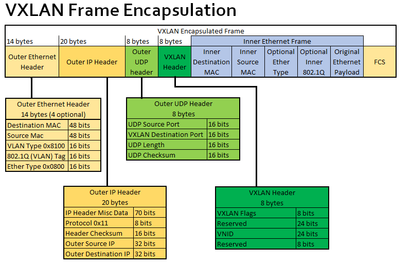
When creating a vtep virtual device for vxlan, we need to manually set the following attributes in the diagram.
- VXLAN destination port: i.e. the port used by the receiver vtep, here the port defined by IANA is 4789, but only calico’s vxlan mode uses this port calico by default, while the default port for cilium/flannel are Linux default 8472.
- VNID: Each VXLAN network interface is assigned an individual VNID
A point-to-point vxlan network architecture is shown below:
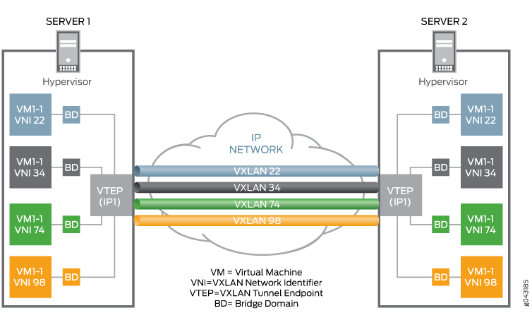
You can see that each VM VM is assigned a unique VNID, and then a VXLAN tunnel is established between the two physical machines via the VTEP virtual network device, and all VMs in the VXLAN network communicate with each other via VTEP.
With the above knowledge, we can establish a point-to-point VXLAN tunnel between two Linux machines with the following command.
 1
 2
 3
 4
 5
 6
 7
 8
 9
10
11
12
13
14
15
16
17
18
19
20
21
22
23
24
25
26
27
28
29
|
# 在主机 A 上创建 VTEP 设备 vxlan0
# 与另一个 vtep 接口 B(192.168.8.101)建立隧道
# 将 vxlan0 自身的 IP 地址设为 192.168.8.100
# 使用的 VXLAN 目标端口为 4789(IANA 标准)
ip link add vxlan0 type vxlan \
    id 42 \
    dstport 4789 \
    remote 192.168.8.101 \
    local 192.168.8.100 \
    dev enp0s8
# 为我们的 VXLAN 网络设置虚拟网段,vxlan0 就是默认网关
ip addr add 10.20.1.2/24 dev vxlan0
# 启用我们的 vxlan0 设备,这会自动生成路由规则
ip link set vxlan0 up

# 现在在主机 B 上运行如下命令,同样创建一个 VTEP 设备 vxlan0,remote 和 local 的 ip 与前面用的命令刚好相反。
# 注意 VNID 和 dstport 必须和前面完全一致
ip link add vxlan0 type vxlan \
    id 42 \
    dstport 4789 \
    remote 192.168.8.100 \
    local 192.168.8.101 \
    dev enp0s8
# 为我们的 VXLAN 网络设置虚拟网段,vxlan0 就是默认网关
ip addr add 10.20.1.3/24 dev vxlan0
ip link set vxlan0 up

# 到这里,两台机器就完成连接,可以通信了。可以在主机 B 上 ping 10.20.1.2 试试,应该能收到主机 A 的回应。
ping 10.20.1.2
|
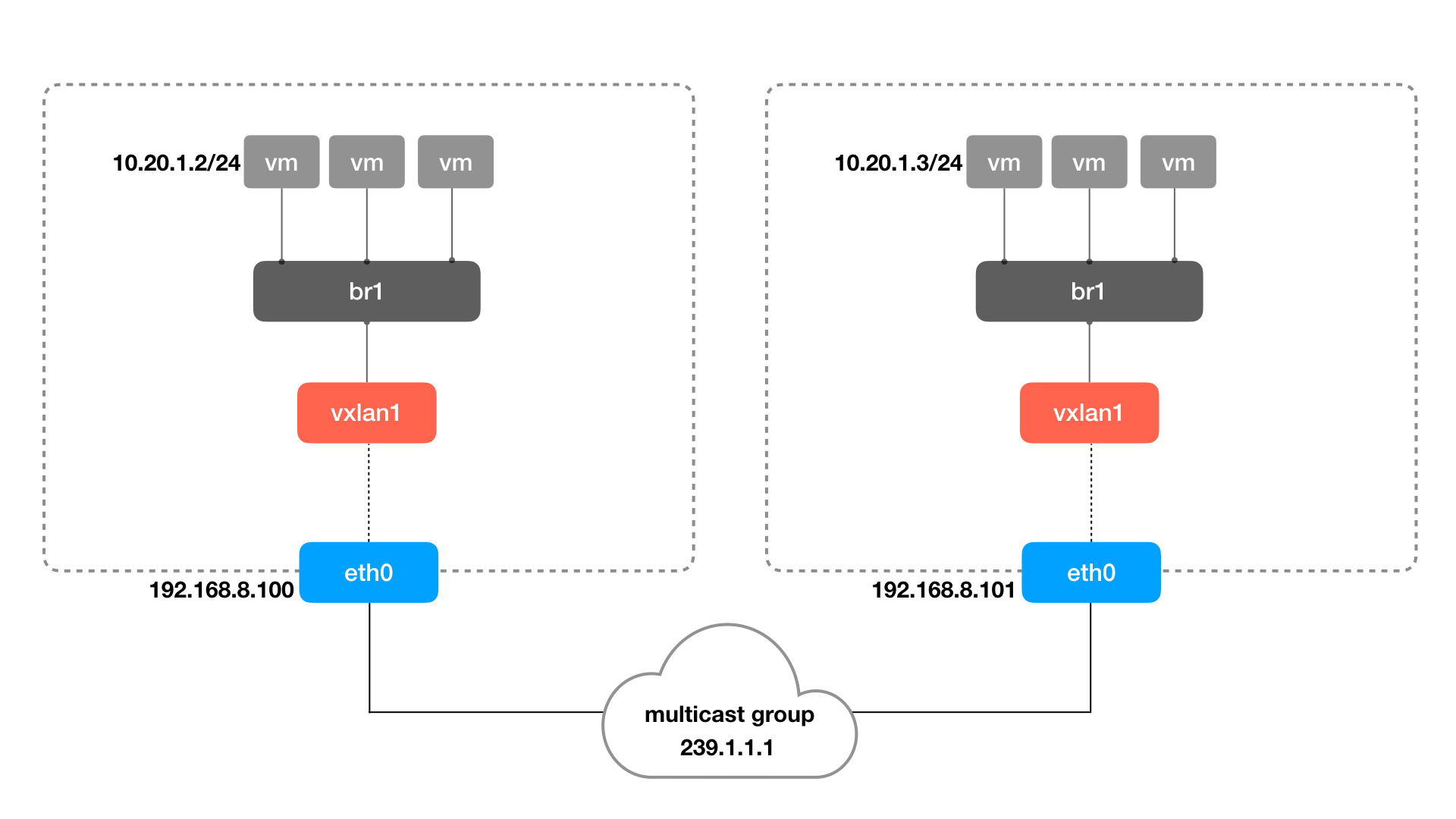
Point-to-point vxlan tunnels are not very useful in practice, and it would be too expensive for every node in the cluster to build vxlan tunnels with each other.
A better approach is to use “multicast mode” vxlan tunnels, where a vtep can tunnel with all the vteps in the group at once. The example command is as follows (information on how to set the multicast address 239.1.1.1 is omitted here)
1
2
3
4
5
6
7
|
ip link add vxlan0 type vxlan \
    id 42 \
    dstport 4789 \
    group 239.1.1.1 \
    dev enp0s8
ip addr add 10.20.1.2/24 dev vxlan0
ip link set vxlan0 up
|
As you can see, it is simply a matter of replacing local_ip/remote_ip with a multicast address. The multicast feature will send the received packets to all vtep interfaces in the group, but only the vtep with the right VNID will process the packet, the other vtep will just discard the data.
Next, to allow all VMs/containers to communicate via vtep, we add a bridge network that acts as a switch between the vtep and the containers. The architecture is as follows.
Use the ip command to create a bridge, network namespace, and veth pairs to form the container network in the above figure.
 1
 2
 3
 4
 5
 6
 7
 8
 9
10
11
12
13
14
15
16
17
18
19
20
21
|
# 创建 br0 并将 vxlan0 绑定上去
ip link add br0 type bridge
ip link set vxlan0 master bridge
ip link set vxlan0 up
ip link set br0 up

# 模拟将容器加入到网桥中的操作
ip netns add container1

## 创建 veth pair,并把一端加到网桥上
ip link add veth0 type veth peer name veth1
ip link set dev veth0 master br0
ip link set dev veth0 up

## 配置容器内部的网络和 IP
ip link set dev veth1 netns container1
ip netns exec container1 ip link set lo up

ip netns exec container1 ip link set veth1 name eth0
ip netns exec container1 ip addr add 10.20.1.11/24 dev eth0
ip netns exec container1 ip link set eth0 up
|
Then do the same on the other machine and create a new container, and the two containers can communicate via vxlan.
A more efficient vxlan implementation than multicast
The biggest problem with multicast is that it doesn’t know the destination of the data, so each vtep sends a copy. If each time data is sent, if it can be precise to the corresponding vtep, it can save a lot of resources.
Another problem is that ARP queries are also multicast, knowing that vxlan itself is an overlay network and the cost of ARP is high.
All the above problems can be solved by a centralized registry (such as etcd), where all the registrations and changes of containers and networks are written to this registry, and then the program automatically maintains the tunnels, fdb tables and ARP tables between vtep.
VIII. Rate of virtual network interfaces
Loopback, like the other virtual network interfaces mentioned in this chapter, is a software emulation of a network device. Is their rate also like the physical link, there is a link layer (such as Ethernet) bandwidth limit?
Many older network devices, for example, are currently only supported up to 100 megabit Ethernet, which determines its bandwidth limit. Even newer devices basically only support up to Gigabit, which is the 1GbE Ethernet standard, so does the virtual network interface mentioned in this article also have this constraint when communicating purely within the local machine? Does it only run up to 1GbE?
Use ethtool to check.
 1
 2
 3
 4
 5
 6
 7
 8
 9
10
11
12
13
|
# docker 容器的 veth 接口速率
> ethtool vethe899841 | grep Speed
        Speed: 10000Mb/s

# 网桥看起来没有固定的速率
> ethtool docker0 | grep Speed
        Speed: Unknown!

# tun0 设备的默认速率貌似是 10Mb/s ?
> ethtool tun0 | grep Speed
        Speed: 10Mb/s

# 此外 ethtool 无法检查 lo 以及 wifi 的速率
|
The next practical test is to give the machine parameters first.
 1
 2
 3
 4
 5
 6
 7
 8
 9
10
11
12
13
14
15
16
17
18
19
20
|
❯ cat /etc/os-release
NAME="openSUSE Tumbleweed"
# VERSION="20210810"
...

❯ uname -a
Linux legion-book 5.13.8-1-default #1 SMP Thu Aug 5 08:56:22 UTC 2021 (967c6a8) x86_64 x86_64 x86_64 GNU/Linux


❯ lscpu
Architecture:                    x86_64
CPU(s):                          16
Model name:                      AMD Ryzen 7 5800H with Radeon Graphics
...

# 内存,单位 MB
❯ free -m
               total        used        free      shared  buff/cache   available
Mem:           27929        4482       17324         249        6122       22797
Swap:           2048           0        2048
|
Tested with iperf3.
 1
 2
 3
 4
 5
 6
 7
 8
 9
10
11
12
13
14
15
16
17
18
19
20
21
22
23
24
25
26
27
28
29
30
31
32
33
34
35
36
37
38
39
40
41
42
43
44
45
46
47
48
49
50
51
52
53
54
55
56
57
58
59
60
61
62
63
|
# 启动服务端
iperf3 -s

-------------
# 新窗口启动客户端,通过 loopback 接口访问 iperf3-server,大概 49Gb/s
❯ iperf3 -c 127.0.0.1
Connecting to host 127.0.0.1, port 5201
[  5] local 127.0.0.1 port 48656 connected to 127.0.0.1 port 5201
[ ID] Interval           Transfer     Bitrate         Retr  Cwnd
[  5]   0.00-1.00   sec  4.46 GBytes  38.3 Gbits/sec    0   1.62 MBytes
[  5]   1.00-2.00   sec  4.61 GBytes  39.6 Gbits/sec    0   1.62 MBytes
[  5]   2.00-3.00   sec  5.69 GBytes  48.9 Gbits/sec    0   1.62 MBytes
[  5]   3.00-4.00   sec  6.11 GBytes  52.5 Gbits/sec    0   1.62 MBytes
[  5]   4.00-5.00   sec  6.04 GBytes  51.9 Gbits/sec    0   1.62 MBytes
[  5]   5.00-6.00   sec  6.05 GBytes  52.0 Gbits/sec    0   1.62 MBytes
[  5]   6.00-7.00   sec  6.01 GBytes  51.6 Gbits/sec    0   1.62 MBytes
[  5]   7.00-8.00   sec  6.05 GBytes  52.0 Gbits/sec    0   1.62 MBytes
[  5]   8.00-9.00   sec  6.34 GBytes  54.5 Gbits/sec    0   1.62 MBytes
[  5]   9.00-10.00  sec  5.91 GBytes  50.8 Gbits/sec    0   1.62 MBytes
- - - - - - - - - - - - - - - - - - - - - - - - -
[ ID] Interval           Transfer     Bitrate         Retr
[  5]   0.00-10.00  sec  57.3 GBytes  49.2 Gbits/sec    0             sender
[  5]   0.00-10.00  sec  57.3 GBytes  49.2 Gbits/sec                  receiver

# 客户端通过 wlp4s0 wifi 网卡(192.168.31.228)访问 iperf3-server,实际还是走的本机,但是速度要比 loopback 快一点,可能是默认设置的问题
❯ iperf3 -c 192.168.31.228
Connecting to host 192.168.31.228, port 5201
[  5] local 192.168.31.228 port 43430 connected to 192.168.31.228 port 5201
[ ID] Interval           Transfer     Bitrate         Retr  Cwnd
[  5]   0.00-1.00   sec  5.12 GBytes  43.9 Gbits/sec    0   1.25 MBytes
[  5]   1.00-2.00   sec  5.29 GBytes  45.5 Gbits/sec    0   1.25 MBytes
[  5]   2.00-3.00   sec  5.92 GBytes  50.9 Gbits/sec    0   1.25 MBytes
[  5]   3.00-4.00   sec  6.00 GBytes  51.5 Gbits/sec    0   1.25 MBytes
[  5]   4.00-5.00   sec  5.98 GBytes  51.4 Gbits/sec    0   1.25 MBytes
[  5]   5.00-6.00   sec  6.05 GBytes  52.0 Gbits/sec    0   1.25 MBytes
[  5]   6.00-7.00   sec  6.16 GBytes  52.9 Gbits/sec    0   1.25 MBytes
[  5]   7.00-8.00   sec  6.08 GBytes  52.2 Gbits/sec    0   1.25 MBytes
[  5]   8.00-9.00   sec  6.00 GBytes  51.6 Gbits/sec    0   1.25 MBytes
[  5]   9.00-10.00  sec  6.01 GBytes  51.6 Gbits/sec    0   1.25 MBytes
- - - - - - - - - - - - - - - - - - - - - - - - -
[ ID] Interval           Transfer     Bitrate         Retr
[  5]   0.00-10.00  sec  58.6 GBytes  50.3 Gbits/sec    0             sender
[  5]   0.00-10.00  sec  58.6 GBytes  50.3 Gbits/sec                  receiver

# 从容器中访问宿主机的 iperf3-server,速度几乎没区别
❯ docker run  -it --rm --name=iperf3-server networkstatic/iperf3 -c 192.168.31.228
Connecting to host 192.168.31.228, port 5201
[  5] local 172.17.0.2 port 43436 connected to 192.168.31.228 port 5201
[ ID] Interval           Transfer     Bitrate         Retr  Cwnd
[  5]   0.00-1.00   sec  4.49 GBytes  38.5 Gbits/sec    0    403 KBytes
[  5]   1.00-2.00   sec  5.31 GBytes  45.6 Gbits/sec    0    544 KBytes
[  5]   2.00-3.00   sec  6.14 GBytes  52.8 Gbits/sec    0    544 KBytes
[  5]   3.00-4.00   sec  5.85 GBytes  50.3 Gbits/sec    0    544 KBytes
[  5]   4.00-5.00   sec  6.14 GBytes  52.7 Gbits/sec    0    544 KBytes
[  5]   5.00-6.00   sec  5.99 GBytes  51.5 Gbits/sec    0    544 KBytes
[  5]   6.00-7.00   sec  5.86 GBytes  50.4 Gbits/sec    0    544 KBytes
[  5]   7.00-8.00   sec  6.05 GBytes  52.0 Gbits/sec    0    544 KBytes
[  5]   8.00-9.00   sec  5.99 GBytes  51.5 Gbits/sec    0    544 KBytes
[  5]   9.00-10.00  sec  6.12 GBytes  52.5 Gbits/sec    0    544 KBytes
- - - - - - - - - - - - - - - - - - - - - - - - -
[ ID] Interval           Transfer     Bitrate         Retr
[  5]   0.00-10.00  sec  58.0 GBytes  49.8 Gbits/sec    0             sender
[  5]   0.00-10.00  sec  58.0 GBytes  49.8 Gbits/sec                  receiver
|
Run iperf3-server in the container and test again.
 1
 2
 3
 4
 5
 6
 7
 8
 9
10
11
12
13
14
15
16
17
18
19
20
21
22
23
24
25
26
27
28
29
30
31
32
33
34
35
36
37
38
39
40
41
42
43
44
45
46
47
48
49
50
51
52
53
54
55
56
57
58
59
60
61
62
63
64
65
66
67
68
69
70
71
72
73
74
75
76
77
78
79
80
81
82
83
84
85
86
|
# 在容器中启动 iperf3-server,并映射到宿主机端口 6201
> docker run  -it --rm --name=iperf3-server -p 6201:5201 networkstatic/iperf3 -s
> docker inspect --format "{{ .NetworkSettings.IPAddress }}" iperf3-server
172.17.0.2
-----------------------------
# 测试容器之间互访的速度,ip 为 iperf3-server 的容器 ip,速度要慢一些。
# 毕竟过了 veth -> veth -> docker0 -> veth -> veth 五层虚拟网络接口
❯ docker run  -it --rm networkstatic/iperf3 -c 172.17.0.2
Connecting to host 172.17.0.2, port 5201
[  5] local 172.17.0.3 port 40776 connected to 172.17.0.2 port 5201
[ ID] Interval           Transfer     Bitrate         Retr  Cwnd
[  5]   0.00-1.00   sec  4.74 GBytes  40.7 Gbits/sec    0    600 KBytes
[  5]   1.00-2.00   sec  4.48 GBytes  38.5 Gbits/sec    0    600 KBytes
[  5]   2.00-3.00   sec  5.38 GBytes  46.2 Gbits/sec    0    600 KBytes
[  5]   3.00-4.00   sec  5.39 GBytes  46.3 Gbits/sec    0    600 KBytes
[  5]   4.00-5.00   sec  5.42 GBytes  46.6 Gbits/sec    0    600 KBytes
[  5]   5.00-6.00   sec  5.39 GBytes  46.3 Gbits/sec    0    600 KBytes
[  5]   6.00-7.00   sec  5.38 GBytes  46.2 Gbits/sec    0    635 KBytes
[  5]   7.00-8.00   sec  5.37 GBytes  46.1 Gbits/sec    0    667 KBytes
[  5]   8.00-9.00   sec  6.01 GBytes  51.7 Gbits/sec    0    735 KBytes
[  5]   9.00-10.00  sec  5.74 GBytes  49.3 Gbits/sec    0    735 KBytes
- - - - - - - - - - - - - - - - - - - - - - - - -
[ ID] Interval           Transfer     Bitrate         Retr
[  5]   0.00-10.00  sec  53.3 GBytes  45.8 Gbits/sec    0             sender
[  5]   0.00-10.00  sec  53.3 GBytes  45.8 Gbits/sec                  receiver

# 本机直接访问容器 ip,走的是 docker0 网桥,居然还挺快
❯ iperf3 -c 172.17.0.2
Connecting to host 172.17.0.2, port 5201
[  5] local 172.17.0.1 port 56486 connected to 172.17.0.2 port 5201
[ ID] Interval           Transfer     Bitrate         Retr  Cwnd
[  5]   0.00-1.00   sec  5.01 GBytes  43.0 Gbits/sec    0    632 KBytes
[  5]   1.00-2.00   sec  5.19 GBytes  44.6 Gbits/sec    0    703 KBytes
[  5]   2.00-3.00   sec  6.46 GBytes  55.5 Gbits/sec    0    789 KBytes
[  5]   3.00-4.00   sec  6.80 GBytes  58.4 Gbits/sec    0    789 KBytes
[  5]   4.00-5.00   sec  6.82 GBytes  58.6 Gbits/sec    0    913 KBytes
[  5]   5.00-6.00   sec  6.79 GBytes  58.3 Gbits/sec    0   1007 KBytes
[  5]   6.00-7.00   sec  6.63 GBytes  56.9 Gbits/sec    0   1.04 MBytes
[  5]   7.00-8.00   sec  6.75 GBytes  58.0 Gbits/sec    0   1.04 MBytes
[  5]   8.00-9.00   sec  6.19 GBytes  53.2 Gbits/sec    0   1.04 MBytes
[  5]   9.00-10.00  sec  6.55 GBytes  56.3 Gbits/sec    0   1.04 MBytes
- - - - - - - - - - - - - - - - - - - - - - - - -
[ ID] Interval           Transfer     Bitrate         Retr
[  5]   0.00-10.00  sec  63.2 GBytes  54.3 Gbits/sec    0             sender
[  5]   0.00-10.00  sec  63.2 GBytes  54.3 Gbits/sec                  receiver

# 如果走本机 loopback 地址 + 容器端口映射,速度就慢了好多
# 或许是因为用 iptables 做端口映射导致的?
❯ iperf3 -c 127.0.0.1 -p 6201
Connecting to host 127.0.0.1, port 6201
[  5] local 127.0.0.1 port 48862 connected to 127.0.0.1 port 6201
[ ID] Interval           Transfer     Bitrate         Retr  Cwnd
[  5]   0.00-1.00   sec  2.71 GBytes  23.3 Gbits/sec    0   1.37 MBytes
[  5]   1.00-2.00   sec  3.64 GBytes  31.3 Gbits/sec    0   1.37 MBytes
[  5]   2.00-3.00   sec  4.08 GBytes  35.0 Gbits/sec    0   1.37 MBytes
[  5]   3.00-4.00   sec  3.49 GBytes  30.0 Gbits/sec    0   1.37 MBytes
[  5]   4.00-5.00   sec  5.50 GBytes  47.2 Gbits/sec    2   1.37 MBytes
[  5]   5.00-6.00   sec  4.06 GBytes  34.9 Gbits/sec    0   1.37 MBytes
[  5]   6.00-7.00   sec  4.12 GBytes  35.4 Gbits/sec    0   1.37 MBytes
[  5]   7.00-8.00   sec  3.99 GBytes  34.3 Gbits/sec    0   1.37 MBytes
[  5]   8.00-9.00   sec  3.49 GBytes  30.0 Gbits/sec    0   1.37 MBytes
[  5]   9.00-10.00  sec  5.51 GBytes  47.3 Gbits/sec    0   1.37 MBytes
- - - - - - - - - - - - - - - - - - - - - - - - -
[ ID] Interval           Transfer     Bitrate         Retr
[  5]   0.00-10.00  sec  40.6 GBytes  34.9 Gbits/sec    2             sender
[  5]   0.00-10.00  sec  40.6 GBytes  34.9 Gbits/sec                  receiver

# 可走 wlp4s0 + 容器端口映射,速度也不慢啊
❯ iperf3 -c 192.168.31.228 -p 6201
Connecting to host 192.168.31.228, port 6201
[  5] local 192.168.31.228 port 54582 connected to 192.168.31.228 port 6201
[ ID] Interval           Transfer     Bitrate         Retr  Cwnd
[  5]   0.00-1.00   sec  4.34 GBytes  37.3 Gbits/sec    0    795 KBytes
[  5]   1.00-2.00   sec  4.78 GBytes  41.0 Gbits/sec    0    834 KBytes
[  5]   2.00-3.00   sec  6.26 GBytes  53.7 Gbits/sec    0    834 KBytes
[  5]   3.00-4.00   sec  6.30 GBytes  54.1 Gbits/sec    0    875 KBytes
[  5]   4.00-5.00   sec  6.26 GBytes  53.8 Gbits/sec    0    875 KBytes
[  5]   5.00-6.00   sec  5.75 GBytes  49.4 Gbits/sec    0    875 KBytes
[  5]   6.00-7.00   sec  5.49 GBytes  47.2 Gbits/sec    0    966 KBytes
[  5]   7.00-8.00   sec  5.72 GBytes  49.1 Gbits/sec    2    966 KBytes
[  5]   8.00-9.00   sec  4.81 GBytes  41.3 Gbits/sec    2    966 KBytes
[  5]   9.00-10.00  sec  5.98 GBytes  51.4 Gbits/sec    0    966 KBytes
- - - - - - - - - - - - - - - - - - - - - - - - -
[ ID] Interval           Transfer     Bitrate         Retr
[  5]   0.00-10.00  sec  55.7 GBytes  47.8 Gbits/sec    4             sender
[  5]   0.00-10.00  sec  55.7 GBytes  47.8 Gbits/sec                  receiver
|
In general, the interfaces loopback, bridge, and veth are basically not speed-limited. veth has a cap of 10000Mb/s (10Gb/s), which feels like a false number, and the actual measured data is basically between 35Gb/s and 55Gb/s, depending on the situation.
The variation in performance is related to the link and type of virtual network device, and perhaps to the difference in default configuration.
In addition, the TUN device is not measured here, and the value of ethtool tun0 is an outrageous 10Mb/s, but it feels unlikely that it is so slow, so we can test it again when we have time.