Today’s network applications have shifted from CPU-intensive to I/O-intensive, and most of the network servers are based on the C-S model, i.e., the Client-Server model, which requires a lot of network communication between the client and the server, which also determines the performance bottleneck of modern network applications: I/O.
The standard I/O interface of the traditional Linux operating system is based on data copy operations, i.e. I/O operations result in data transfer between buffers in the OS kernel address space and buffers defined in the user process address space. The biggest advantage of setting buffers is that it reduces the number of disk I/O operations. If the requested data is already stored in the OS cache memory, then there is no need to perform actual physical disk I/O operations; however, traditional Linux I/O is deeply CPU-dependent for data copy operations during data transfer, which means that the I/O process requires the CPU to perform data copy This results in significant system overhead and limits the ability of the operating system to efficiently perform data transfer operations.
I/O is the key to determining the performance bottleneck of a web server, and the traditional Linux I/O mechanism leads to a large number of data copy operations and loss of performance, so we urgently need a new technology to solve the problem of large number of data copies, and the answer is Zero-copy.
Computer Memory
Since we are going to analyze Linux I/O, we cannot fail to understand the various types of memory in a computer.
Memory is one of the core components of a computer, and in a completely ideal state, memory should have all three of the following characteristics:
- fast enough: memory should be accessed faster than the CPU can execute an instruction, so that the CPU’s efficiency is not limited by memory
- large enough capacity: the capacity can store all the data needed by the computer
- cheap enough: inexpensive, all types of computers can be equipped
But the reality is often harsh, our current computer technology cannot meet all three conditions at the same time, so modern computer memory design uses a hierarchical structure.
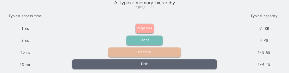
From top to bottom, the types of memory in modern computers are: registers, cache, main memory and disk, which have decreasing speed and increasing capacity. The fastest access is to registers, which are as fast as CPUs because they are made of the same materials as CPUs, and there is no time delay for CPU access to registers, however, because they are expensive and therefore have extremely small capacities. Regardless of whether it is 32-bit or 64-bit, the register capacity is less than 1 KB, and registers must also be managed by software itself.
The second layer is the cache, which we usually understand as CPU cache L1, L2, and L3. Generally, L1 is exclusive to each CPU, L3 is shared by all CPUs, and L2 is designed to be exclusive or shared in one of two modes depending on the architecture design, for example, Intel’s multi-core chips use a shared L2 mode while AMD’s multi-core chips use an exclusive L2 mode.
The third layer is the main memory, also known as main memory, often called Random Access Memory (RAM). It is the internal memory that exchanges data directly with the CPU. It can be read and written at any time (except when it is refreshed) and is very fast, and is usually used as a temporary data storage medium for the operating system or other running programs.
Finally, there is the disk, the disk and main memory compared to the cost of each binary bit is two orders of magnitude lower, so the capacity than it will be much larger, often on GB, TB, and the problem is that the access speed is about three orders of magnitude slower than the main memory. Mechanical hard drives are slow mainly because the mechanical arm needs to keep moving between metal platters and wait for the disk sectors to rotate under the head before it can perform read and write operations, so it is inefficient.
Main memory is the most important part of the operating system for I/O operations, and the vast majority of the work is done in the memory buffers of the user processes and the kernel, so we next need to learn some of the principles related to main memory in advance.
Physical Memory
The physical memory we have been referring to is the third type of computer memory mentioned above, RAM main memory, which exists in a computer in the form of memory sticks embedded in the memory slots on the motherboard and is used to load various programs and data for the CPU to run and use directly.
Virtual Memory
There is a philosophy in computing as sacred as the Ten Commandments of Moses: " any problem in computer science can be solved by adding an indirect intermediate layer", which can be seen shining through from memory management, network models, concurrent scheduling and even hardware architecture, and virtual memory is one of the perfect practices of this philosophy.
Virtual memory is a very important memory abstraction in modern computers, mainly to address the growing memory needs of applications: the capacity of modern physical memory has grown very fast, but it still cannot keep up with the growth of applications’ demand for main memory, and there is still not enough memory for applications, so a way to resolve the capacity gap between the two is needed.
Computer management of multi-program memory access has gone through static relocation –> dynamic relocation –> swapping technology –> virtual memory, the most primitive multi-program memory access is to access the absolute memory address directly, which is almost a completely unavailable solution, because if each program accesses the physical memory address directly, for example, when two programs execute the following instructions concurrently.
This assembly indicates that the value of 2 is deposited at address 1000:0, and then the value of that address is taken out and multiplied by 2 in the later logic, and the final value deposited in the ax register is 4. If the value deposited in the cx register by the second program is 3, then the value obtained by the first program from the ax register may be 6 when executed concurrently, which is completely wrong, and the dirty data obtained is at most If another program writes some dangerous instructions to a specific address and another program takes it out, it may cause the whole system to crash. Therefore, to ensure that processes do not interfere with each other, each user process needs to know in real time which memory addresses are currently being used by other processes, which is undoubtedly a nightmare for those who write programs.
Therefore, manipulating absolute memory addresses is a completely infeasible solution, so we have to use manipulating relative memory addresses. We know that each process will have its own process address, starting from 0, and can access memory through relative addresses, but this has the same problem, or a similar problem as before. For example, there are two programs A and B of size 16KB, and now they are both loaded into memory with memory address segments A’s first instruction is jmp 1024, and at address 1024 is a mov instruction, and the next instruction is add, which does addition based on the previous mov instruction, while B’s first instruction is jmp 1028, which should have been a mov instruction at address 1028 relative to B. But since the two programs share segment registers, they use their relative addresses but still operate on the absolute memory address, so B jumps to execute the add instruction, which crashes due to illegal memory operations.
There is a static relocation technique to solve this problem. It works in a very simple and brutal way: when program B is loaded to address 16384, all relative memory addresses of B are added to 16384, so that when B executes jmp 1028, it actually executes jmp 1028+16384, and can jump to the correct memory address to execute the correct instruction, but this technique is not universal and has an impact on the performance of loading programs into memory.
But the exclusive address space poses a new problem: how to achieve the same relative address of different processes pointing to different physical addresses? This was first achieved using dynamic relocation techniques, which is a relatively simple method of mapping address space to physical memory. The basic principle is to equip each CPU with two special hardware registers: the base address register and the boundary register, which are used to dynamically store the starting physical memory address and length of each program, such as the two programs A and B in the previous article, when A is running the base address register and the boundary register will be stored in 0 and 16384 respectively, while when B is running the two registers will be stored in 16384 and 32768 respectively. Then each time the specified memory address is accessed, the CPU will automatically add the value in the base address register to the memory address before sending the address to the memory bus to get a real physical memory address, and also check whether the address is overflowed according to the value in the boundary register, and if so, generate an error to abort the program. Dynamic relocation solves the problem of slow loading speed caused by static relocation techniques, but there is a new problem: each access to memory requires addition and comparison operations, which can be fast in themselves, but addition operations are slower due to the problem of incoming transfer time, unless special circuitry is used.
Then there is the swapping technique, which simply means that the program is dynamically swapped between memory and disk, so that when a process is to be run, the code and data segments of the program are transferred into memory, and then the program is sealed and stored on disk, and so on. Why all this trouble? Because the prerequisite for the previous two relocation techniques is that the computer memory is large enough to load the address space of all the processes to be run into main memory in order to run them concurrently, but this is not always the case. The first one is a simple swap technique.
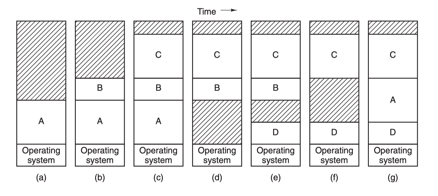
Process A is first swapped into memory, then processes B and C are started and also swapped into memory, then A is swapped from memory to disk, then a new process D is called into memory and uses the memory space vacated after A exits, and finally A is swapped back into memory again. Since the memory layout has changed, A’s memory address is relocated either by software or by hardware (base and boundary registers) during the swapping process, in most cases by hardware.
Another technique for handling memory overload is virtual memory, which is more complex and efficient than swapping and is the latest and most widely used memory abstraction technique.
The core principle of virtual memory is to set up a “contiguous” virtual address space for each program, divide this address space into multiple pages with contiguous address ranges, and map these pages to physical memory, which is dynamically mapped to physical memory during program operation. When a program refers to a section of address space in physical memory, the hardware immediately performs the necessary mapping; when a program refers to a section of address space that is not in physical memory, the operating system is responsible for loading the missing section into physical memory and re-executing the failed instruction.
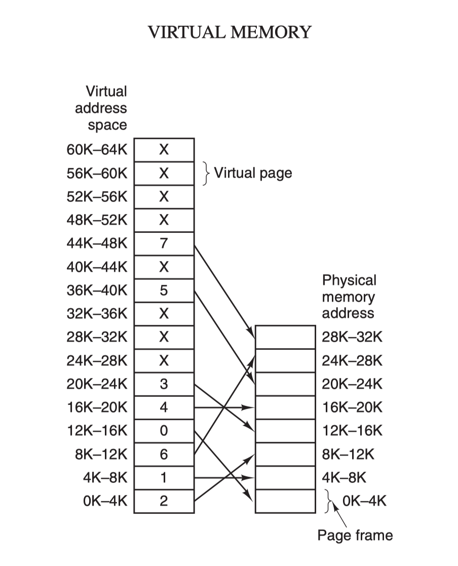
The virtual address space is divided into fixed-size cells called pages, which correspond to page frames in physical memory. The two are generally the same size, 4KB as in the figure above, but in practice computer systems are generally 512 bytes to 1 GB, which is the paging technique of virtual memory. Because of the virtual memory space, each process is allocated 4GB (32-bit architecture), and it is impossible to allocate 4GB of physical memory to all running processes, so the virtual memory technology also requires the use of the swapping technology introduced earlier, which only allocates and maps the memory currently in use during the process, and writes back to disk the data that is not in use temporarily. The data that is not used temporarily is written back to disk as a copy and then read into memory when it is needed, dynamically swapping data between disk and memory.
In fact, virtual memory technology is, from a certain point of view, a new technology that combines the base address register and the boundary register. It allows the address space of the entire process to be mapped to physical memory in smaller cells without the need to relocate the code and data addresses for the program.
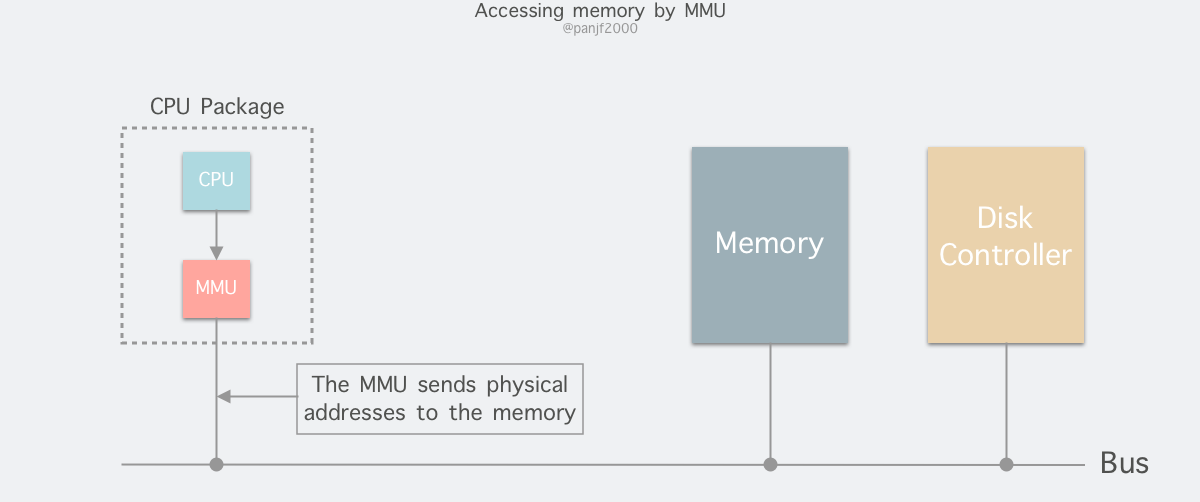
The memory addresses generated by the process during runtime are virtual addresses. If the computer does not introduce virtual memory as a memory abstraction technique, the CPU sends these addresses directly to the memory address bus and directly accesses the physical address with the same value as the virtual address; if virtual memory technology is used, the CPU sends these virtual addresses through the address bus to the Memory Management Unit (MMU) The MMU maps the virtual addresses to physical addresses and then accesses the physical memory through the memory bus.
The virtual address (for example, 16-bit address 8196=0010 000000000100) is divided into two parts: virtual page number (high part) and offset (low part), the virtual address is converted to physical address through the page table (page table), the page table consists of page table items, page table items are stored in the page frame number, modify bit, access bit, protection bit and “in/out The page table consists of page table entries, which hold information such as page frame number, modify bit, access bit, protect bit and “in/out” bit. Mathematically speaking, the page table is a function, where the input is the virtual page number and the output is the physical page frame number.
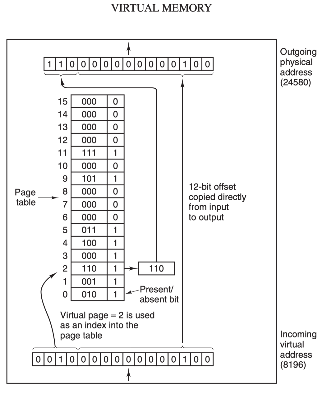
When the MMU performs an address translation, if the “in/out” bit of the page table entry is 0, the page is not mapped to a real physical page frame, a out-of-page interrupt is raised and the CPU is trapped in the OS kernel, then the OS selects a page to swap out through the page replacement algorithm to make room for the new page to be transferred in. If the modified bit in the page table entry of the page to be swapped out has been set, i.e. updated, then it is a dirty page and needs to be written back to disk to update the copy of the page on disk, if the page is “clean”, i.e. unmodified, then the old page to be swapped out can be overwritten with the new page to be swapped in.
Finally, another concept that needs to be understood is the Translation Lookaside Buffer (TLB), also known as the fast table, which is used to speed up virtual address mapping because of the paging mechanism of virtual memory, the page table is generally a fixed storage area in memory, resulting in the process accessing memory through the MMU than directly accessing memory once more memory The TLB can be simply understood as a cache of page tables, which holds the most frequently accessed page table items, and as it is generally implemented in hardware, it is extremely fast. If it hits and the access operation of the page table item is legal, the corresponding physical page frame number is directly retrieved from the TLB and returned; if it does not hit, it penetrates to the memory page table and replaces one of the existing TLBs with the latest page table item from the memory page table for the next cache hit.
So far, we have finished introducing a number of computer memory abstraction techniques, including virtual memory. Other contents of virtual memory, such as multi-level page tables for large memory, inverted page tables, and page replacement algorithms to deal with missing page interrupts, etc., will be introduced in a separate article when we have a chance, or you can check the relevant information first to understand, so we will not go into depth here.
User State and Kernel State
Generally speaking, nine times out of ten when we write a program to manipulate Linux I/O, we are transferring data between user space and kernel space, so it is important to understand the concept of user state and kernel state in Linux.
First, user state and kernel state.
At a macro level, the architecture of the Linux operating system is divided into a user state and a kernel state (or user space and kernel). The kernel is essentially software - it controls the computer’s hardware resources and provides the environment in which upper-level applications (processes) run. The user state is the runtime space for upper-level applications (processes), which must rely on the resources provided by the kernel, including but not limited to CPU resources, storage resources, I/O resources, and so on.
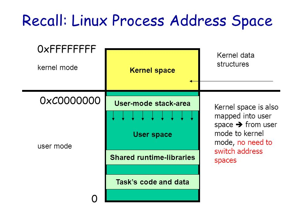
The core of the operating system is the kernel, which is independent from ordinary applications and has access to protected memory space and all rights to the underlying hardware devices. To ensure that user processes cannot directly manipulate the kernel (kernel) and to ensure the security of the kernel, the worry system divides the virtual space into two parts, one for kernel space and one for user space. For the Linux operating system, the highest 1G bytes (from the virtual address 0xC0000000 to 0xFFFFFFFF), which is used by the kernel, is called kernel space, while the lower 3G bytes (from the virtual address 0x00000000 to 0xBFFFFFFF), which is used by individual processes, is called user space.
Because operating system resources are limited, if too many operations are performed to access resources, they will inevitably consume too many system resources, and if these operations are not differentiated, they are likely to cause conflicts in accessing resources. Therefore, in order to reduce the conflict of access and use of limited resources, one of the design philosophies of Unix/Linux is that different operations are given different levels of execution, which is the concept of so-called privilege. The Intel x86 CPU provides four privilege levels from 0 to 3, the smaller the number, the higher the privilege, and the Linux operating system mainly uses two privilege levels 0 and 3, corresponding to the kernel state and user state respectively. Processes running in user state are extremely limited in the operations they can perform and the resources they can access, while processes running in kernel state can perform any operation and are not limited in the use of resources. Many programs start in user state, but during execution, some operations need to be executed with kernel privileges, which involves a process of switching from user state to kernel state. For example, the memory allocation function malloc() in the C library specifically uses the sbrk() system call to allocate memory, and when malloc calls sbrk() it involves a switch from user state to kernel state, and similar functions like printf(), which calls the wirte() system call to output a string, and so on.
When a user process is running in the system, it spends most of its time in the user state, and needs to switch to the kernel state when it needs help from the operating system to perform some operations that the user state does not have the privilege and ability to perform. So how does a user process switch to the kernel state to use those kernel resources? The answer is: 1) a system call (trap), 2) an exception and 3) an interrupt.
- Syscall : An operation initiated by a user process. The user process initiates a system call to actively request a switch to the kernel state, and after falling into the kernel, it is up to the operating system to operate the system resources and return to the process when it is done.
- Exception : An operation that is reactive and whose timing cannot be predicted by the user process. When an exception occurs during the user process (e.g., an instruction goes wrong), this triggers a switch from the currently running process to the kernel-related process that handles the exception, i.e., a switch to the kernel state. Exceptions include all kinds of errors caused by program operations such as divide by 0, buffer overflow, missing page, etc.
- Interrupt: When the peripheral device completes the operation requested by the user, it will send a corresponding interrupt signal to the CPU, and then the CPU will suspend the execution of the next instruction to be executed and switch to the handler corresponding to the interrupt signal. Interrupts include I/O interrupts, external signal interrupts, clock interrupts caused by various timers, and so on. Interrupts are similar to exceptions in that they are handled through the interrupt vector table to find the appropriate handler. The difference is that interrupts come from outside the processor and are not caused by any specific instruction, while exceptions are the result of executing the current instruction.
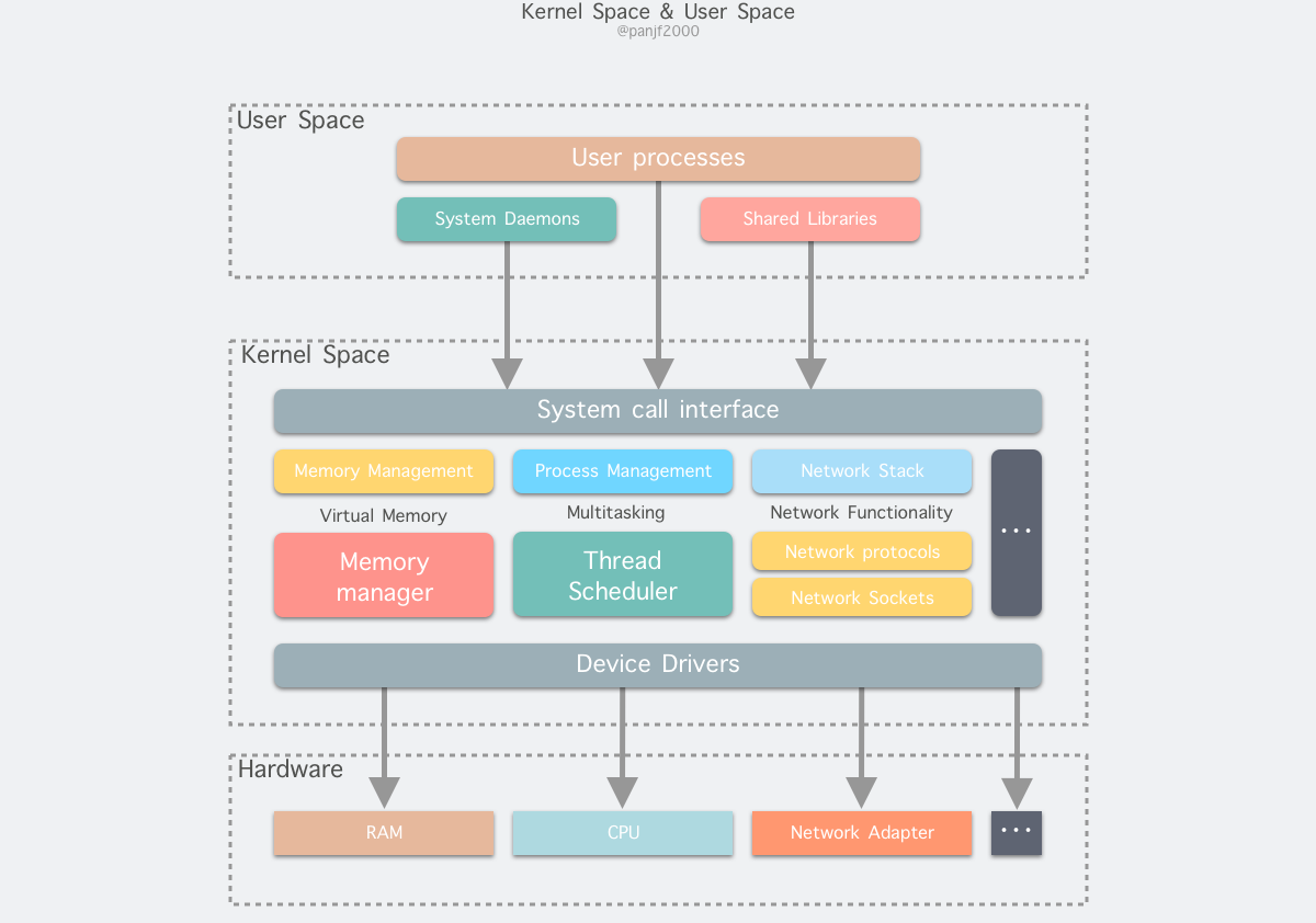
From the above analysis, we can conclude that the internal hierarchy of Linux can be divided into three main parts.
- user space.
- the kernel space.
- hardware.
Linux I/O
I/O buffers
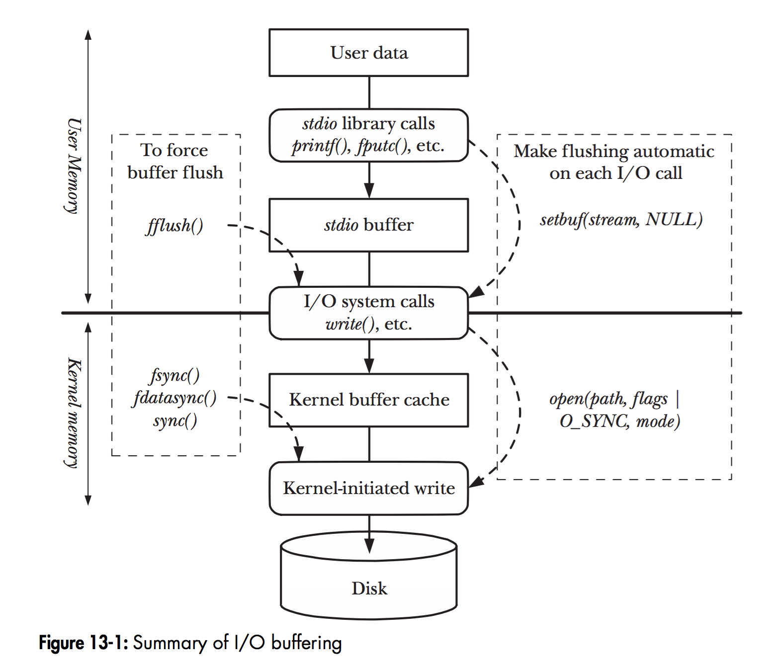
In Linux, when a program calls various file manipulation functions, the flow of User Data arriving at the Disk is shown in the figure above.
The diagram depicts the hierarchy of file operation functions and the location of the memory cache layer in Linux. The solid black line in the middle is the demarcation line between the user state and the kernel state.
read(2)/write(2) are the most basic I/O read/write system calls in Linux, and we will definitely come across them when developing programs that manipulate I/O. Between these two system calls and the real disk read/write, there is a buffer cache called Kernel buffer cache. The I/O cache in Linux can be subdivided into two: Page Cache and Buffer Cache, which are actually two sides of the same coin that make up the Linux Kernel Buffer Cache.
- Read Disk : The kernel will first check if the data is already cached in the
Page Cache, if so, read it directly from this memory buffer and return it, if not, it will penetrate to the disk to read it, and then cache it in thePage Cachefor the next cache hit. - write to disk: The kernel writes the data directly to the
Page Cacheand marks the corresponding page as dirty, adds it to the dirty list, and then returns it directly. The kernel will periodically flush the dirty list of page cache to disk to ensure the final consistency between page cache and disk.
The Page Cache periodically eliminates old pages and loads new ones through page replacement algorithms such as LRU. As you can see, the so-called I/O buffer cache is a layer of buffers between the kernel and peripherals such as disks and NIC(Network Interface Controller) to improve read and write performance.
Before Linux did not support virtual memory technology, there was no concept of pages, so Buffer Cache was based on the smallest unit of the operating system that reads and writes to the disk - the block, and all disk block operations were accelerated by Buffer Cache. Therefore, Page Cache was introduced to cache the contents of Linux files, mainly as a cache for file data on the file system to improve read and write performance, commonly for read()/write() operations on files, and also for block devices after mapping through mmap(), that is, in fact, Page Cache is responsible for most of the caching of block device files. The Buffer Cache is used by the system to cache the data of the block when the system reads and writes to the block device, and is actually responsible for all I/O accesses to the disk.
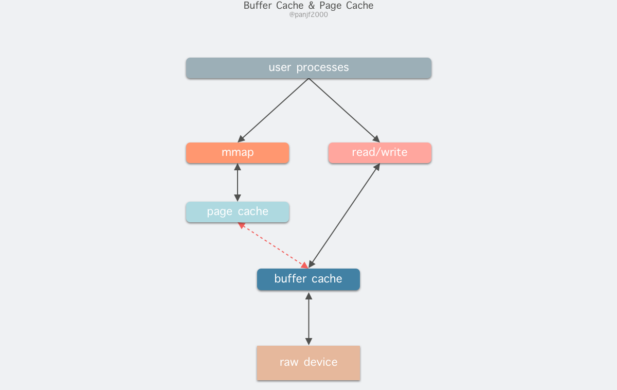
Because Buffer Cache is a cache of finer-grained device blocks, and Page Cache is a virtual memory-based page cell cache, it will still be based on Buffer Cache, which means that if you are caching file content data you will be caching two copies of the same data in memory, which will result in two copies of the same file being saved, which is redundant and inefficient. Another problem is that after calling write, the valid data is in the Buffer Cache, not in the Page Cache. This leads to possible inconsistencies in the file data accessed by mmap. To get around this problem, all disk file system-based writes need to call the update_vm_cache() function, which updates the Buffer Cache to the Page Cache after the write call. Because of these design drawbacks, the kernel unified the two after Linux 2.4, and Buffer Cache no longer exists as a standalone, but as a fusion in Page Cache.
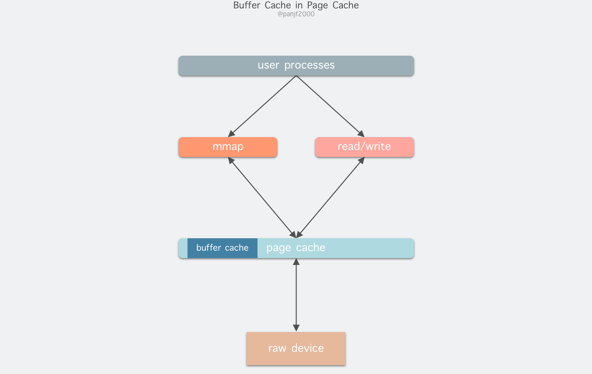
Once fused, the Page Cache and Buffer Cache can be operated in unison: the file I/O cache is handled by the Page Cache, while the underlying RAW device actually handles the data when it is refreshed in block units of the Buffer Cache.
I/O Mode
In Linux or other Unix-like operating systems, there are three general I/O modes.
- program control I/O
- Interrupt-driven I/O
- DMA I/O
I’ll explain each of these three I/O modes in detail below.
Program Control I/O
This is the simplest type of I/O mode, also called busy waiting or polling: the user initiates a system call, gets stuck in the kernel state, the kernel translates the system call into a procedure call corresponding to the device driver, then the device driver starts an I/O loop to check the device to see if it is ready or not, usually indicated by a return code, and after the I/O is finished, the device driver sends the data to the specified place and returns, cutting back to the user state.
For example, initiating the system call read().
Interrupt Driven I/O
The second I/O mode is implemented using interrupts.
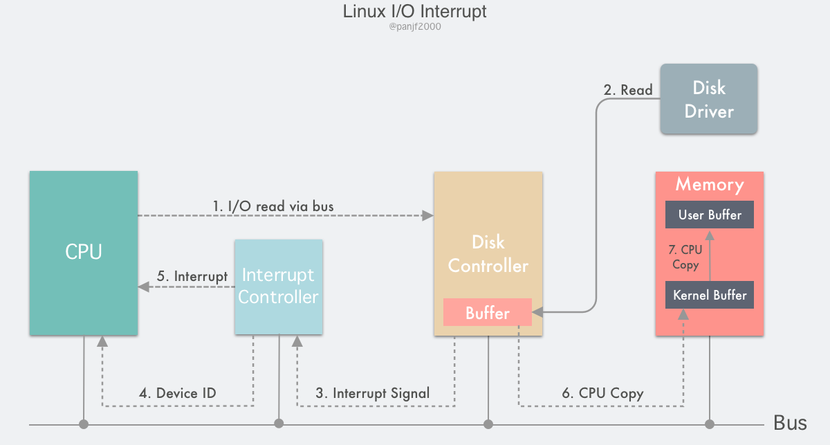
The flow is as follows.
- the user process initiates a
read()system call to read the disk file, gets stuck in the kernel state and has its CPU write a notification signal to the device register via the device driver, informing the device controller (in our case, the disk controller) that it wants to read the data - the disk controller starts the disk read process and copies the data from the disk to the disk controller buffer
- After the copy is completed, the disk controller sends an interrupt signal over the bus to the interrupt controller. If the interrupt controller has an interrupt on hand or a higher priority interrupt that arrives at the same time as the interrupt signal, the interrupt signal will be ignored and the disk controller will continue to send interrupts until the interrupt controller accepts it.
- the interrupt controller receives the interrupt signal from the disk controller and deposits a disk device number via the address bus, indicating that the device to be concerned about this interrupt is the disk
- The interrupt controller places a disk interrupt signal to the CPU.
- After receiving the interrupt signal, the CPU stops its current work, presses the current PC/PSW registers into the stack to save the scene, then takes out the device number from the address bus, finds the entry address of the interrupt service contained in the interrupt vector by the number, presses it into the PC register, starts running the disk interrupt service, copies the data from the buffer of the disk controller to the kernel buffer in the main memory.
- Finally, the CPU copies the data from the kernel buffer to the user buffer, completes the read operation,
read()returns, and switches back to the user state.
DMA I/O
The performance of the concurrent system depends on the efficient scheduling and use of CPU resources. If we look back at the flow of the interrupt-driven I/O mode, we can see that the data copying in steps 6 and 7 is done by the CPU itself, which means that the CPU is completely occupied during these two data copying stages and cannot handle other work. The data copy in step 7 is from the kernel buffer to the user buffer, which is in the main memory, so this step can only be done by the CPU itself, but the data copy in step 6 is from the disk controller’s buffer to the main memory, which is the data transfer between two devices.
DMA, also known as Direct Memory Access, is a method used to provide high-speed data transfer between peripherals and memory or between memory and memory. The whole process does not require the CPU to participate, and the data is moved directly through the DMA controller for fast copies, saving the CPU’s resources for other tasks.
Today, most computers are equipped with DMA controllers, and DMA technology supports most peripherals and memories. With the DMA mechanism, the I/O process of a computer can be more efficient.
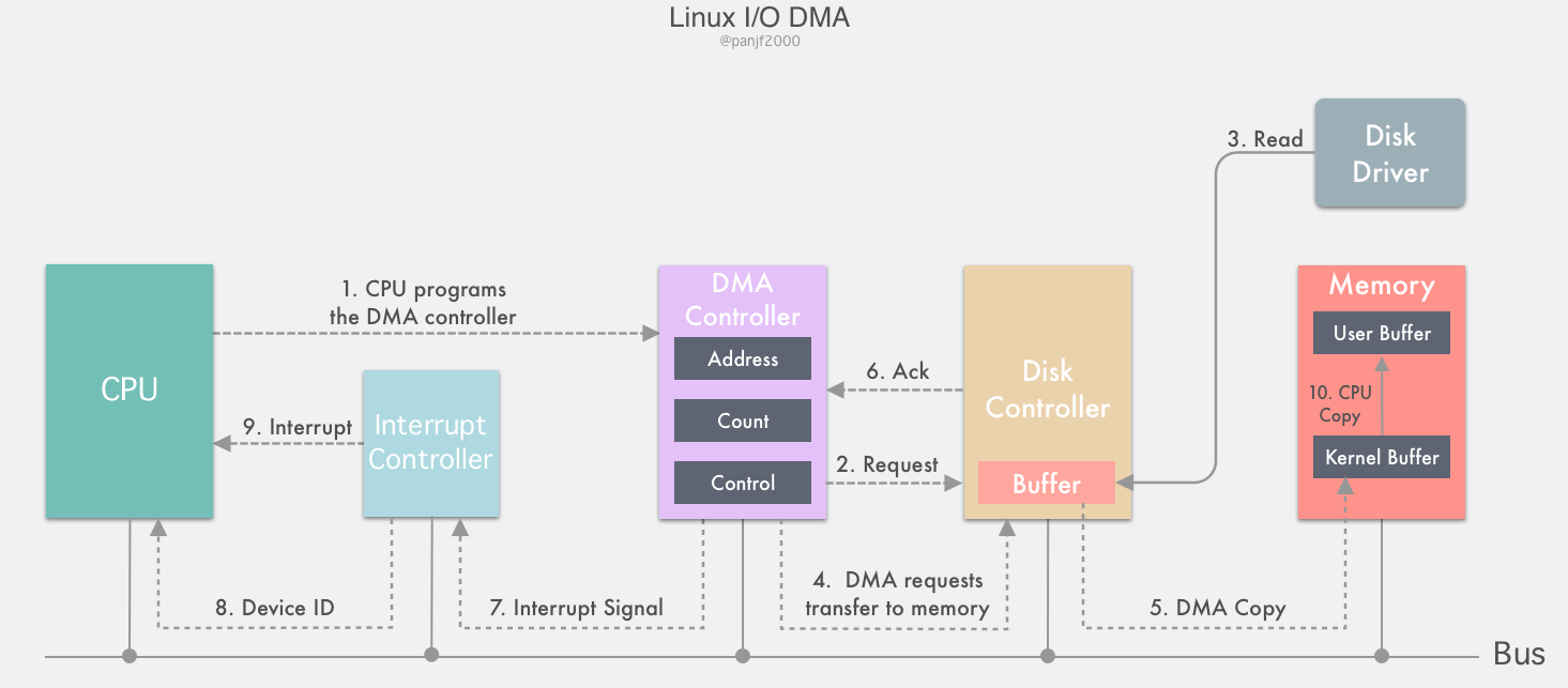
The DMA controller contains several internal registers that can be read and written by the CPU: a main memory address register MAR (which holds the address of the main memory to be exchanged), a peripheral address register ADR (which holds the device code of the I/O device, or the addressing information of the device information store), a byte count register WC (which counts the total number of words of data transferred), and one or more control registers.
- The user process initiates a
read()system call to read the disk file, plunges into the kernel state and is programmed by its CPU by setting the registers of the DMA controller: it writes the addresses of the kernel buffer and the disk file to the MAR and ADR registers, respectively, and then writes the number of bytes it expects to read to the WC register, starting the DMA controller - The DMA controller knows that the peripheral to be read is a certain address of the disk based on the information in the ADR register, and issues a command to the disk controller to notify it to read data from the disk into its internal buffer
- the disk controller starts the disk read process, copies the data from the disk to the disk controller buffer, and checks the checksum of the data in the buffer, if the data is valid, then the DMA is ready to start
- The DMA controller initiates the DMA transfer by sending a read request signal to the disk controller through the bus, which is the same as the read request sent by the CPU to the disk controller in the previous section on interrupt-driven I/O. It does not know or care whether the read request is from the CPU or the DMA controller.
- the DMA controller will then direct the disk controller to transfer the data to the address in the MAR register, which is the kernel buffer.
- After the data transfer is completed, an ack is returned to the DMA controller, and the value in the WC register is subtracted from the corresponding data length, and if the WC is not yet 0, steps 4 through 6 are repeated until the number of bytes in the WC equals 0.
- The DMA controller receiving the ack signal will send an interrupt signal to the interrupt controller via the bus. If the interrupt controller has an interrupt in process or a higher priority interrupt arriving at the same time as the interrupt signal, the interrupt signal will be ignored and the DMA controller will continue to send the interrupt signal until the interrupt controller accepts it.
- The interrupt controller receives the interrupt signal from the disk controller and deposits a device number of the main memory via the address bus, indicating that the device to be concerned about this interrupt is the main memory.
- The interrupt controller signals a DMA interrupt to the CPU.
- After the CPU receives the interrupt signal, it stops the current work, presses the current PC/PSW registers into the stack to save the site, then takes out the device number from the address bus, finds the entry address of the interrupt service contained in the interrupt vector by the number, presses it into the PC register, starts to run the DMA interrupt service, copies the data from the kernel buffer to the user buffer, finishes the read operation,
read()returns and switches back to user state
Traditional I/O read and write modes
Traditional I/O reading and writing in Linux is done through the read()/write() system calls. read() reads data from memory (disk, NIC, etc.) into the user buffer, and write() writes data from the user buffer to memory.
A complete read of a disk file and then a write out to the NIC with the underlying transfer process is as follows.
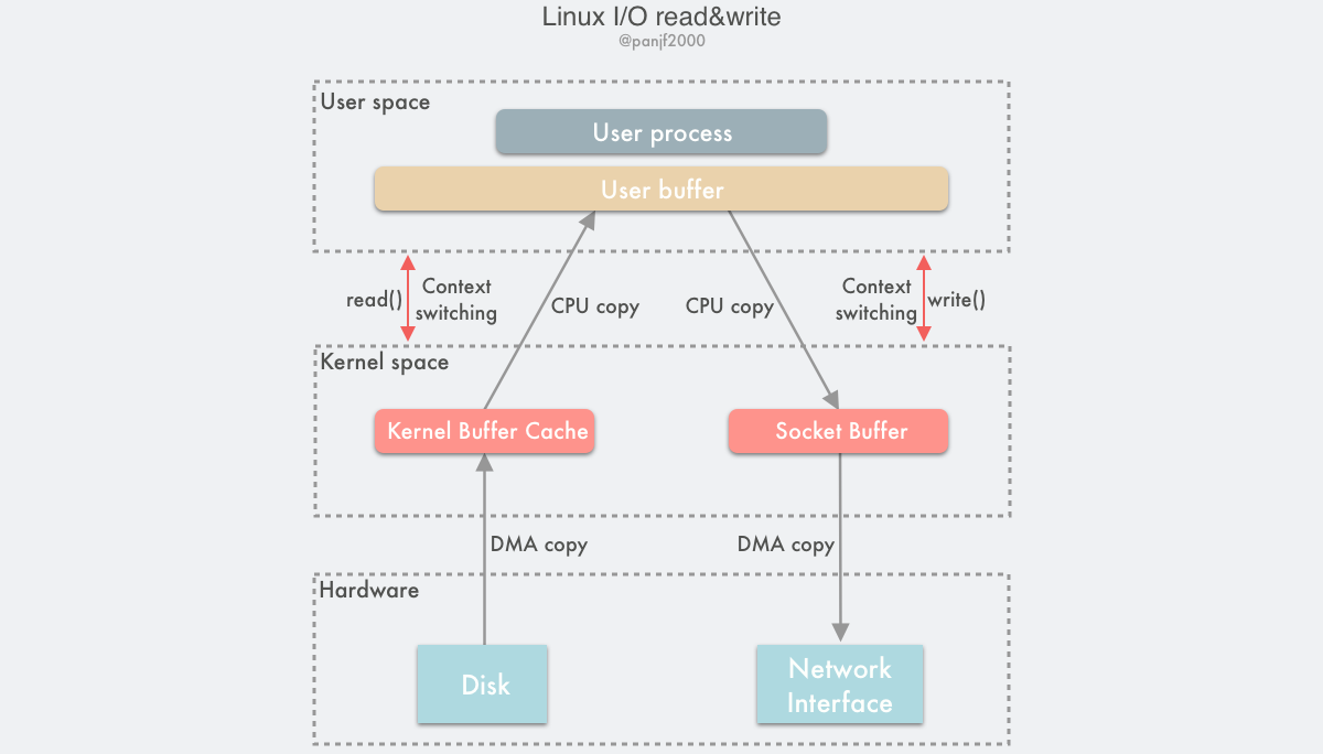
You can clearly see that 4 user and kernel context switches are triggered here, namely read()/write() calls and return switches, 2 DMA copies, and 2 CPU copies, adding up to 4 copy operations.
By introducing DMA, we have reduced the number of CPU copies in Linux I/O from 4 to 2. However, CPU copies are still a costly operation and have a significant impact on system performance, especially in those frequent I/O scenarios, where a lot of performance is lost due to CPU copies, and we need to further optimize to reduce or even avoid CPU copies altogether.
Zero-copy
What is Zero-copy?
Wikipedia explains it as follows.
“Zero-copy” describes computer operations in which the CPU does not perform the task of copying data from one memory area to another. This is frequently used to save CPU cycles and memory bandwidth when transmitting a file over a network.
What does Zero-copy do?
- Reduce or even completely avoid data copy operations between the OS kernel and the user application address space, thus reducing the system overhead of user-kernel context switching.
- Reduce or even completely avoid data copy operations between OS kernel buffers.
- Helps user processes access the hardware storage interface to manipulate data directly, bypassing the OS kernel space.
- Use DMA instead of CPU to perform data copying between hardware interface and kernel buffer, thus freeing up CPU to perform other tasks and improving system performance.
What are the ways to implement zero-copy?
Since the concept of zero-copy was introduced, there has been a proliferation of related implementations. But so far, there is no single zero-copy technology that can meet the needs of all scenarios, or the classic computer saying: “There is no silver bullet”!
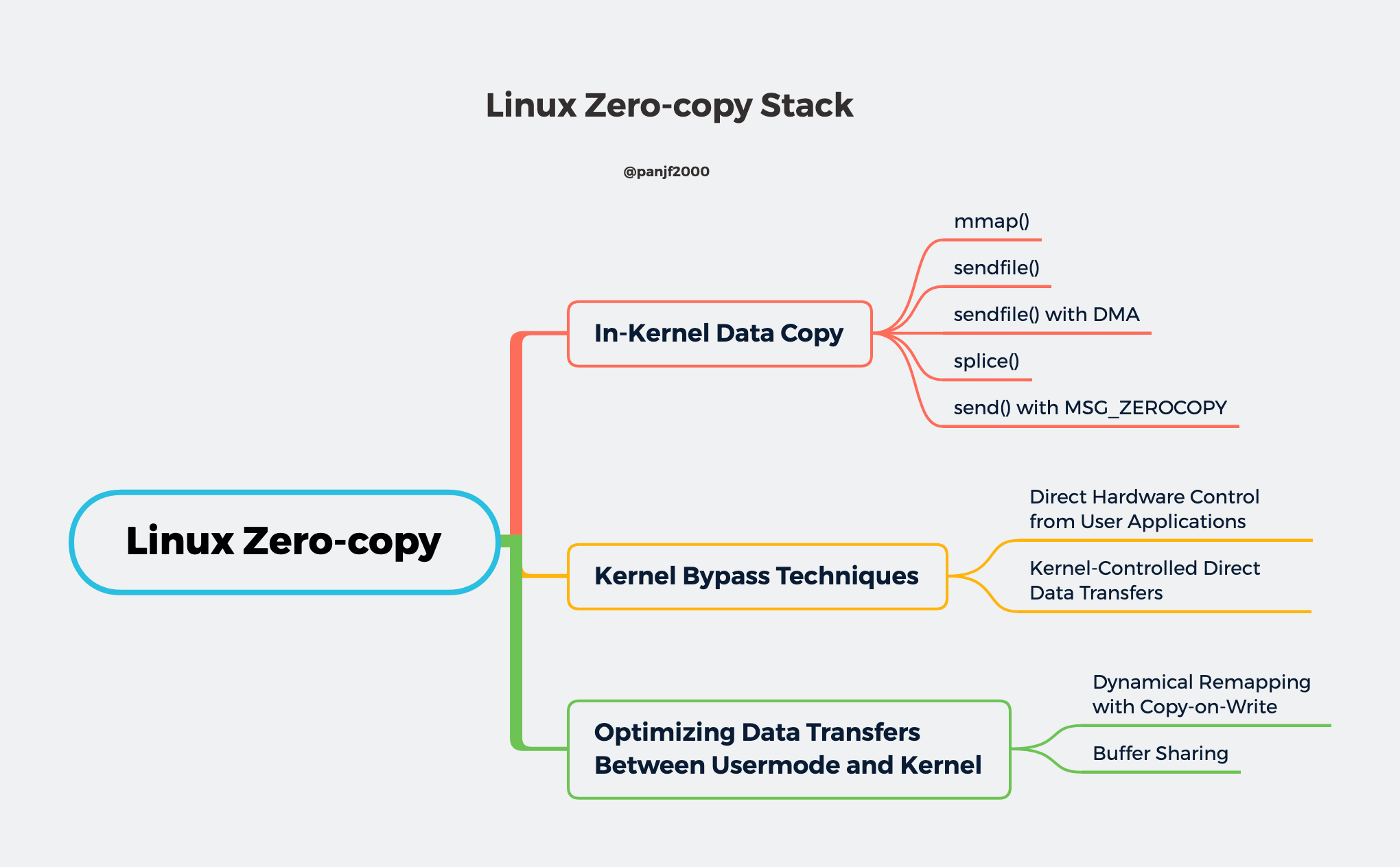
On the Linux platform, there are also many zero-copy technologies, old and new, which may exist in different kernel versions, and many of them may have been greatly improved or replaced by newer implementations, which can be grouped into the following three categories according to their core ideas.
- Reduce or even avoid data copying between user space and kernel space: In some scenarios where the user process does not need to access and process the data during data transfer, data transfer between Linux’s
Page Cacheand the user process’s buffer can be completely avoided, allowing data copying to be done entirely in the kernel, or even more subtly by Even more clever ways to avoid data copying in the kernel are possible. This is typically done by adding new system calls, such as mmap(), sendfile(), and splice() in Linux. - Direct I/O bypassing the kernel: Allows user-state processes to transfer data directly to the hardware, bypassing the kernel, with the kernel only taking care of some administrative and auxiliary tasks during the transfer. This approach is actually somewhat similar to the first one, which also tries to avoid data transfer between user space and kernel space, except that the first approach puts the data transfer process in the kernel state, while this approach directly bypasses the kernel and hardware communication, with similar effects but completely different principles.
- Transfer optimization between kernel buffers and user buffers: This approach focuses on optimizing the CPU copy between the user process buffers and the OS page cache. This approach continues the traditional way of communication, but is more flexible.
Reduce or even avoid data copying between user space and kernel space
mmap()
A simple implementation is to replace read() with another Linux system call mmap() during a read or write. mmap() is also known as a memory map: a section of the user buffer in the user process space is mapped to the kernel buffer where the file is located.
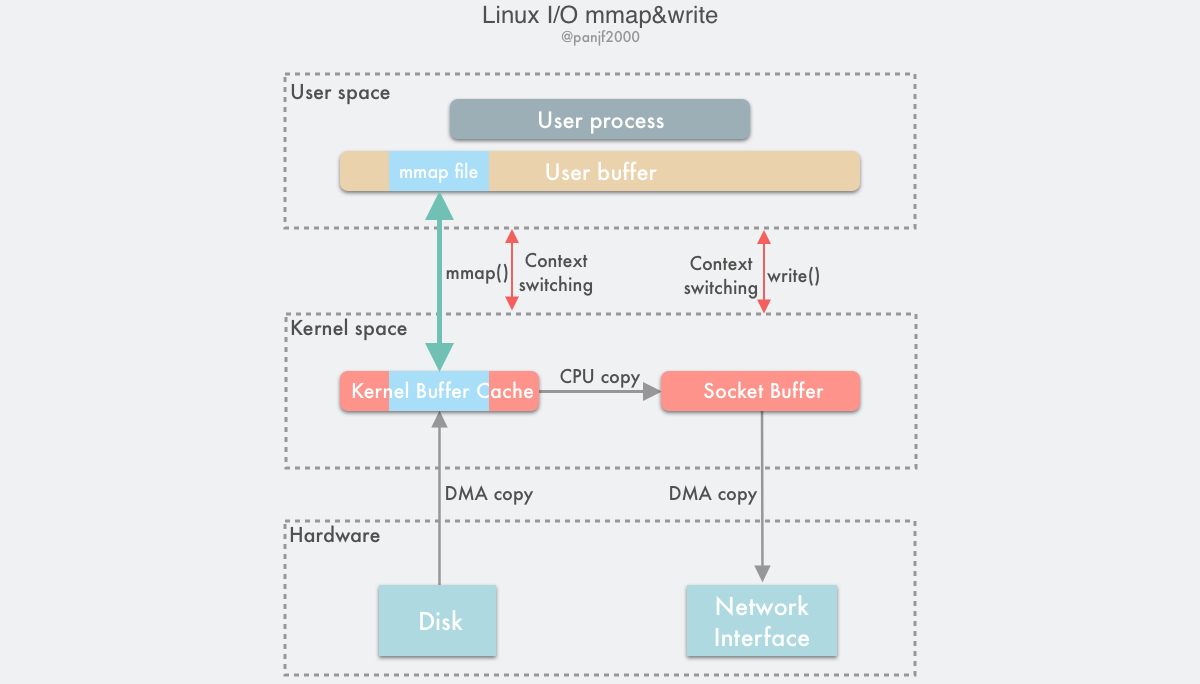
The entire flow of the mmap() call with write() instead of read() is as follows.
- the user process calls
mmap(), which plunges from the user state into the kernel state and maps the kernel buffer to the user buffer - the DMA controller copies data from the hard disk to the kernel buffer
mmap()returns and the context switches from kernel state back to user state- user process calls
write()and tries to write the file data to the socket buffer in the kernel, falling into the kernel state again - CPU copies the data from the kernel buffer to the socket buffer
- the DMA controller copies the data from the socket buffer to the NIC to complete the data transfer
write()returns and the context switches from kernel state back to user state
In this way, there are two advantages: first, it saves memory space because the memory on the user process is virtual and does not really occupy physical memory, but is mapped to the kernel buffer where the file is located, thus saving half of the memory footprint; second, it eliminates one CPU copy, as compared to traditional Linux I/O reads and writes, the data does not need to be forwarded through the user process anymore. Instead, the copy is done directly in the kernel. So the number of copies after using mmap() is 2 DMA copies and 1 CPU copy, which adds up to 3 copy operations, saving one CPU copy and half of the memory compared to traditional I/O, but since mmap() is also a system call, there are still 4 user and kernel state switches.
Because mmap() saves both CPU copies and memory, it is more suitable for large file transfer scenarios. Although mmap() is fully POSIX-compliant, it is not perfect, because it does not always achieve the desired data transfer performance. Firstly, it still requires a CPU copy during data transfer, and secondly, the memory mapping technique is an overhead virtual storage operation: it requires modifying the page table and replacing the cache in the current TLB with the file data in the kernel buffer to maintain the consistency of the virtual memory map. However, since memory maps are usually for relatively large data areas, the overhead of memory mapping is much lower than the overhead of CPU copying for the same size of data. For example, if another process suddenly truncates the file during the transfer of the mmap() –> write() calls, the user process will be killed by a SIGBUS interrupt signal from the bus for accessing an illegal address and a core dump will be generated. There are two solutions.
- Set up a signal handler specifically for handling SIGBUS signals, this handler will return directly,
write()will return the number of bytes written normally without being interrupted by SIGBUS, and the errno error code will be set to success. However, this is actually a cover-up solution, because the message brought by the BIGBUS signal However, this is actually a cover-up solution, because the BIGBUS signal brings the message that something serious is wrong with the system and we choose to ignore it, which is generally not recommended. - The problem is solved by the kernel’s file lease lock (this is what Linux calls it, on Windows it is called an opportunity lock), which is a relatively better approach. When another process tries to truncate a file that is currently being transferred by the user process, the kernel will send the user a real-time signal: RT_SIGNAL_LEASE signal, which tells the user that the kernel is breaking the read/write lease lock you put on that file, and the `write() The file lease lock needs to be set before memory mapping of the file, and finally released before the user process finishes.
sendfile()
In version 2.1 of the Linux kernel, a new system call sendfile() has been introduced.
From a functional point of view, this system call combines the two system calls mmap() + write() into one, achieving the same effect while simplifying the user interface, as other Unix-like systems like BSD, Solaris and AIX have similar implementations, and even Windows has a similar API function TransmitFile.
out_fd and in_fd represent write and read file descriptors respectively. in_fd must be a file descriptor pointing to a file and must support class mmap() memory mapping and cannot be of socket type, while out_fd can only be a file descriptor pointing to a socket until Linux kernel version 2.6.33, and from 2.6 off_t is a pointer to the offset of in_fd, indicating where sendfile() should start reading from in_fd. The last count parameter is the total number of bytes to be transferred by this call.
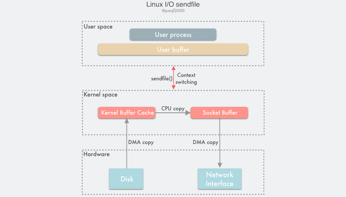
The flow of a data read/write using sendfile() is as follows
- the user process calls
sendfile()to fall into the kernel state from the user state. - the DMA controller copies the data from the hard disk to the kernel buffer.
- the CPU copies the data from the kernel buffer to the socket buffer; 4. the DMA controller copies the data from the kernel buffer to the socket buffer.
- the DMA controller copies the data from the socket buffer to the NIC to complete the data transfer.
sendfile()returns and the context switches from kernel state back to user state.
Based on sendfile(), there are 2 DMA copies and 1 CPU copy during the whole data transfer, which is the same as mmap() + write(), but since sendfile() is just a system call, it has less context switching overhead between user state and kernel state than the former. At this point, the wise reader will start to ask: “Does sendfile() encounter similar file truncation problems as mmap() + write()?” Unfortunately, the answer is yes. sendfile() has the same file truncation problem, but happily, sendfile() is not only cleaner to use than mmap() + write() in terms of its interface, but it also handles file truncation much more gracefully: if a file truncation occurs during sendfile(), the sendfile() system call will be returned to the user process with the number of bytes transferred before it was interrupted and errno will be set to success, eliminating the need for the user to set up a signal handler in advance, although you can set one up for personalized processing, and there is no need to set a lease lock on the file descriptor in advance, as before, because the end result is the same.
Another advantage of sendfile() over mmap() is that the data never crosses the boundary between user and kernel state during transfer, thus greatly reducing the storage management overhead. Even so, sendfile() is still a narrowly applicable technology, and the most suitable scenario is basically a static file server. According to a mailing list by Linus and other kernel maintainers in 2001, the decision to implement sendfile() on Linux was made only because it had already been implemented on other operating systems and was already being used by the famous Apache Web server, so it was decided that it would be compatible with the Apache Web server. Linus agreed to implement this technology on Linux, and the simplicity of the sendfile() implementation was well integrated with the rest of the Linux kernel.
However, sendfile() itself has significant problems, mainly from different perspectives.
- the first is that the interface is not standardized, so that the implementation of
sendfile()on Linux is not the same as that on other Unix-like systems. - secondly, due to the asynchronous nature of network transmission, it is difficult to implement the technology for interfacing with
sendfile()at the receiving end, so there has been no such technology implemented at the receiving end. - finally, from the performance point of view, because
sendfile()still requires CPU participation in the process of transferring the disk file from the kernel buffer (page cache) to the socket buffer, which makes it difficult to avoid contamination of the CPU cache by the transferred data.
Also, it should be noted that sendfile() was not originally designed to handle large files, so if you need to handle very large files, you can use another system call, sendfile64(), which supports addressing and offsetting the contents of larger files.
sendfile() with DMA Scatter/Gather Copy
The sendfile() technique introduced in the previous section has reduced the number of CPU copies to only 1 during a read/write, but people are always greedy and ungrateful, now if you want to remove the only CPU copy, is there a way?
Of course there is! By introducing a new hardware support, we can wipe out this one remaining CPU copy: Linux introduced scatter/gather for DMA in kernel version 2.4, and modified the sendfile() code to make it compatible with DMA. scatter makes it possible to eliminate the need to store the DMA copy in a contiguous piece of memory. scatter allows the DMA controller to collect the data stored everywhere based on a small amount of meta-information: a buffer descriptor containing the memory address and data size, and eventually reduce it to a complete network packet that is copied directly to the NIC instead of the socket buffer, avoiding a final CPU copy.
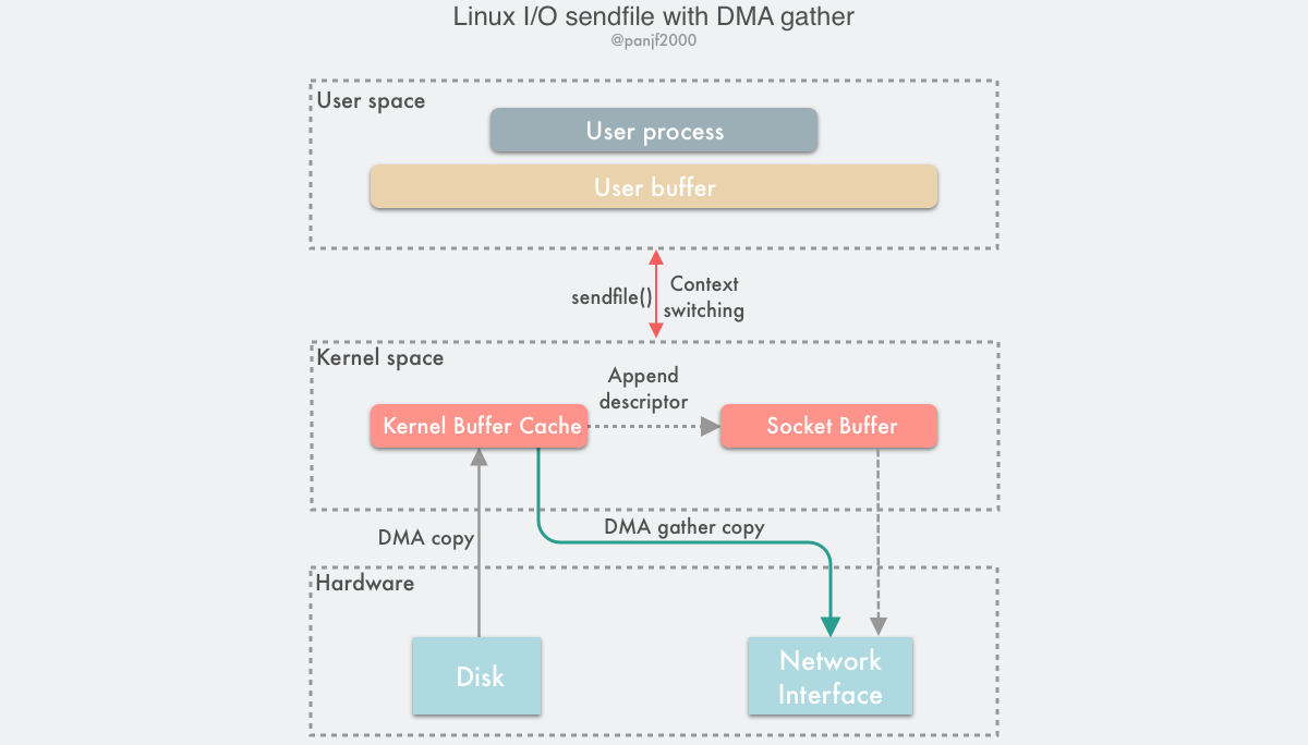
The data transfer process of sendfile() + DMA gather is as follows.
- the user process calls
sendfile()to fall from the user state to the kernel state. - the DMA controller uses the scatter function to copy data from the hard disk to the kernel buffer for discrete storage.
- the CPU copies the buffer descriptor containing the memory address and data length to the socket buffer, and the DMA controller is able to generate the header and tail of the network packet data packet based on this information
- the DMA controller uses the scatter-gather function to start collecting discrete data from the kernel buffer and grouping packets based on the memory address and data size in the buffer descriptor, and finally copies the network packet data directly to the NIC to complete the data transfer.
sendfile()returns and the context switches from kernel state back to user state.
Based on this solution, we can remove the only remaining CPU copy (technically there will still be one, but since this time the CPU copies only the minuscule meta information, the overhead is almost negligible), theoretically, the data transfer process will no longer involve the CPU, so the CPU cache will no longer be polluted, and the CPU will no longer be needed to calculate the data checksum. The CPU can perform other business computation tasks and parallelize the I/O tasks of DMA, which can greatly improve the system performance.
splice()
The sendfile() + DMA Scatter/Gather zero-copy scheme is efficient but has two drawbacks.
- this option requires the introduction of new hardware support.
- although the output file descriptor of
sendfile()can already support any type of file descriptor after Linux kernel version 2.6.33, the input file descriptor can still only point to files.
These two drawbacks limit the applicability of the sendfile() + DMA Scatter/Gather scheme. For this reason, Linux introduced a new system call splice() in version 2.6.17, which is functionally very similar to sendfile(), but enables the transfer of data between two file descriptors of any type; in the underlying implementation, splice() has one less CPU copy than sendfile(). which is equivalent to sendfile() + DMA Scatter/Gather, completely eliminating the CPU copy during data transfer.
The splice() system call function is defined as follows.
fd_in and fd_out also represent the input and output file descriptors respectively, and one of these two file descriptors must point to the pipe device, which is also a not-so-friendly restriction, although the Linux kernel development officials promised from the time this system call was introduced that it might be refactored to remove this restriction in the future, but after they made this promise, it was as good as dead. Now, more than 10 years later, there is still no news…
off_in and off_out are pointers to the offsets of fd_in and fd_out respectively, indicating where the kernel reads and writes data from, len indicates the number of bytes the call expects to transfer, and finally flags is the system call’s flag option bitmask, which sets the behavior of the system call and consists of 0 or more of the following values combined by the ‘or’ operation.
- SPLICE_F_MOVE: instructs
splice()to try to just move memory pages instead of copying them; setting this value does not necessarily mean that memory pages will not be copied; whether they are copied or moved depends on whether the kernel can move memory pages from the pipeline, or whether the memory pages in the pipeline are intact; the initial implementation of this flag had a lot of bugs, so it has been in place since Linux version 2.6.21, but it has been retained because it may be reimplemented in a future version. - SPLICE_F_NONBLOCK: instructs
splice()not to block I/O, i.e. makes thesplice()call a non-blocking call that can be used to implement asynchronous data transfers, but note that it is also best to pre-mark the two file descriptors for data transfers as non-blocking I/O with O_NONBLOCK, otherwise thesplice()call may still be blocked. - SPLICE_F_MORE: informs the kernel that more data will be transferred with the next
splice()system call, this flag is useful for scenarios where the output side is a socket.
splice() is based on Linux’s pipe buffer mechanism, so the two incoming file descriptors of splice() require that one of them be a pipe device, a typical use of splice() is.
Diagram of the data transfer process.
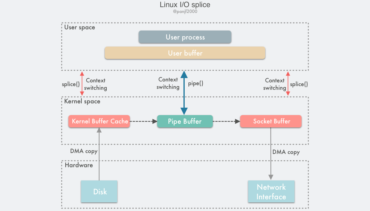
Using splice() to complete a read/write of a disk file to the NIC is as follows.
- the user process calls
pipe(), which plunges from the user state into the kernel state, creates an anonymous one-way pipe,pipe()returns, and the context switches from the kernel state back to the user state - the user process calls
splice()to fall from the user state to the kernel state - The DMA controller copies data from the hard disk to the kernel buffer, “copies” it from the write side of the pipe into the pipe,
splice()returns, and the context returns from the kernel state to the user state - the user process calls
splice()again and falls from the user state to the kernel state - The kernel “copies” the data from the read side of the pipe to the socket buffer, and the DMA controller copies the data from the socket buffer to the NIC
splice()returns and the context switches from kernel state back to user state
I believe that after reading the above read/write flow, the reader will be very confused: what about splice(), which is an improved version of sendfile()? sendfile() only requires one system call, but splice() requires three. That’s all, but there’s a pipeline in the middle, and it has to be copied twice in kernel space, what kind of improvement is that?
This was my reaction when I first learned about splice(), but after I learned more about it, I gradually realized the mystery, let me explain it in detail.
First, let’s understand pipe buffer pipe, pipe is a channel used on Linux for communication between processes, the pipe has two ends: the write end and the read end, from the perspective of the process, the pipe behaves as a FIFO byte stream ring queue.
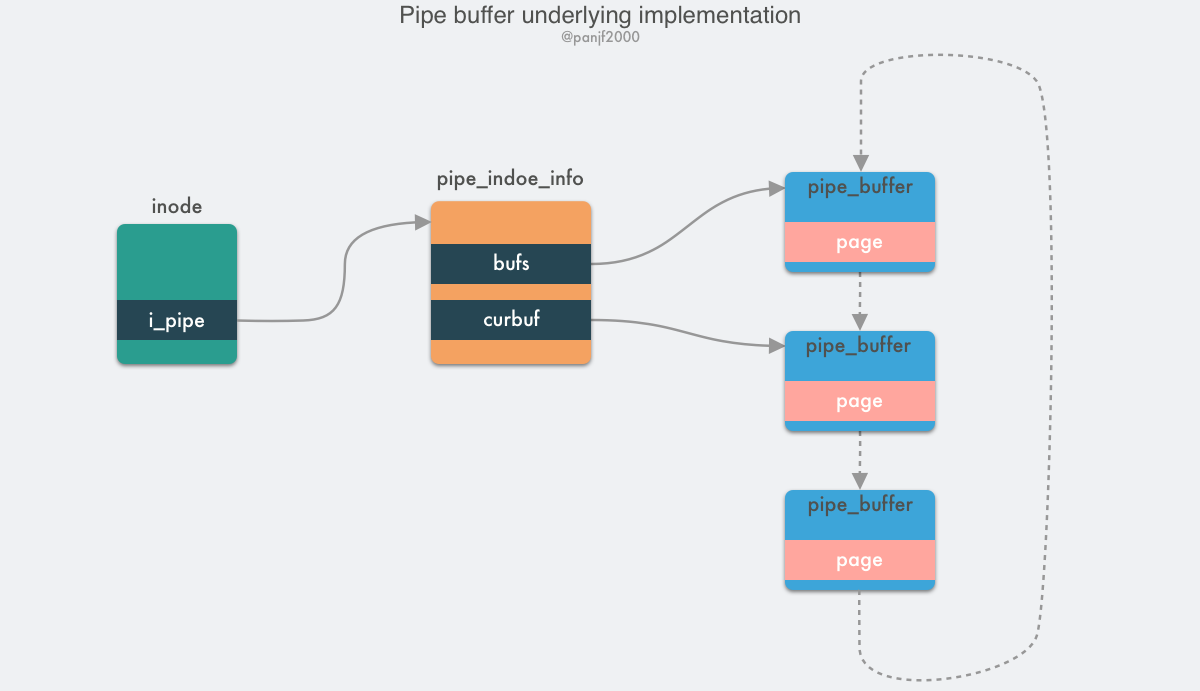
A pipeline is essentially a file in memory, i.e., it is still essentially a Linux-based VFS user process that can create an anonymous pipeline through the pipe() system call, and after it is created, there are two inodes of the VFS file structure that point to its write side and read side, and return the corresponding two file descriptors, through which the user process reads and writes to the pipeline. The capacity of the pipe is one virtual memory page, i.e. 4KB, and the total size is usually 16 pages, based on its ring structure, the pages of the pipe can be recycled to improve memory utilization. Linux encapsulates the pipeline pages in a pipe_buffer structure, and a pipe_inode_info structure is stored in the inode field of the file structure to refer to the pipeline, which stores a lot of meta information needed to read and write to the pipeline, the head pointer page of the ring queue, synchronization mechanisms such as mutual exclusion locks and waiting queues when reading and writing.
|
|
The pipe_buffer stores the page, offset and length of the data in memory, and uses these three values to locate the data. Note that the page here is not a virtual memory page, but a physical memory page frame, because the pipeline is a cross-process channel, so it cannot use virtual memory to represent it, but can only use the physical memory page frame to locate the data; the normal read/write operation of the pipe is done by pipe_write()/pipe_read(), and the data transfer is done by reading/writing the data to the pipe_buffer in the ring queue.
splice() is based on the pipe buffer implementation, but it is zero-copy when transferring data through the pipe, because it does not actually write and read data in the pipe buffer using pipe_write()/pipe_read() when writing and reading, but rather by assigning the physical memory page frame pointers, offsets and The data is “copied” by assigning the physical memory frame pointer, offset and length of the data in the memory buffer to the corresponding three fields in the pipe_buffer mentioned above, i.e. only the meta information such as the memory address of the data is copied.
The internal implementation of splice() in the Linux kernel source code is the do_splice() function, while writing to and reading from the pipe is done through do_splice_to() and do_splice_from() respectively, so let’s focus on parsing the source code of the write pipe, which is do_splice_to(). The Linux kernel version I have at hand is v4.8.17, so we will analyze it based on this version. As for the read source code function do_splice_from(), the principle is similar, so we can use it as an example.
The call chain for splice() to write data to the pipe: do_splice() –> do_splice_to() –> splice_read().
|
|
Go to do_splice_to() and then call splice_read().
|
|
in->f_op->splice_read This function pointer has different implementations depending on the type of file descriptor, for example, in here is a file, so it’s generic_file_splice_read(), if it’s a socket, it’s sock_splice_read(), other The other types will also have corresponding implementations, but in any case we will be using the generic_file_splice_read() function, which will go on to call the internal function __generic_file_splice_read to do the following.
- searching in the page cache page cache to see if the content of the file we want to read is already in the cache, if it is then use it directly, otherwise if it does not exist or only some of the data is in the cache, allocate some new memory pages and perform the read-in data operation, while increasing the reference count of the page frame.
- based on these memory pages, initialize the splice_pipe_desc structure, which holds the address meta-information that will hold the file data, containing the address of the physical memory page frame, the offset, and the data length, which are the values of the three locality data needed for the pipe_buffer.
- finally, call
splice_to_pipe(), the instance of the structuresplice_pipe_descis the function entry.
|
|
Here you can clearly see that the so-called splice() write to pipe does not actually copy the data, but plays a tricky operation: it only copies the memory address pointer instead of actually copying the data. So, the data splice() is not really copied in the kernel, so the splice() system call is also a zero copy.
Another point to note is that as mentioned before, the capacity of the pipe is 16 memory pages, which means 16 * 4KB = 64 KB, which means that it is better not to write more than 64 KB to the pipe at a time, otherwise splice() will block, unless pipe2() is used when creating the pipe and the pipe is set to non-blocking by passing in the O_NONBLOCK property.
Even though splice() avoids the real copy overhead by using the memory address pointer, it uses an extra pipeline to complete the data transfer, which means two more system calls than sendfile(), which adds to the context switching overhead. Why not just create the pipeline in the kernel and call splice() twice, then expose the user to only one system call? Actually, since splice() is a lower threshold implementation of zero-copy using pipes rather than hardware than sendfile() + DMA Scatter/Gather, the underlying implementation of sendfile() has been replaced with splice() since then.
As for why the splice() API itself is still used in this way, it is because the Linux kernel development team has been trying to remove this restriction based on pipes, but I don’t know what has been put on hold, so the API has not changed, and we can only wait for the kernel team to remember this one day, and then refactor it so that it no longer relies on pipes. If your business scenario is suitable for using splice(), but you are performance sensitive and don’t want to create and destroy pipe buffer buffers too often, then you can refer to the optimization scheme used by HAProxy when using splice(): pre-allocate a pipe buffer pool to cache pipes, and each time you call spclie(), go to the cache pool to fetch a pipe and put it back when you’re done with it, so as to recycle it and improve performance.
send() with MSG_ZERO_COPY
In v4.14 of 2017, the Linux kernel accepted the patch of the zero-copy function (MSG_ZEROCOPY) implemented by Google engineer Willem de Bruijn in send(), the generic send interface for TCP network messages, which allows user processes to send data from the user buffer to the network socket via zero-copy. This new technique is more advanced than the previous zero-copy methods, which require the user process not to process the data but to forward it directly to the target file descriptor. In his paper, Willem de Bruijn shows that using netperf to send large packets, performance is improved by 39%, while the performance of sending data in an online environment is improved by 5% to 8%. The official documentation states that this feature is usually only significant when sending large packets of about 10KB. Initially, this feature was only supported for TCP, and UDP was only supported after kernel v5.0.
The usage pattern of this function is as follows.
The first step is to set a SOCK_ZEROCOPY option for the socket you want to send data to, and then set a MSG_ZEROCOPY option when you call send() to send the data. The official argument is that the send() API was designed to be compatible with a previous bug: the previous implementation of send() ignored unknown options, and in order to be compatible with programs that may have accidentally set the MSG_ZEROCOPY option, it is necessary to set the option twice. ZEROCOPY option, so it was designed to be set in two steps. But I guess there is another possibility: it is to provide more flexible usage mode for users, because this new feature may only have significant performance improvement in large packet scenario, but the real scenario is very complex, not only all large or all small packets, but also a mix of large and small packets, so users can call setsockopt() first to set SOCK_ ZEROCOPY option, and then choose whether to use MSG_ZEROCOPY for zero-copy transfer when calling send() according to the network packet size in the actual business scenario.
Since send() may send data asynchronously, one special point to note when using MSG_ZEROCOPY is that the buffer cannot be reused or released immediately after calling send() because the data in the buffer may not have been read by the kernel, so it is necessary to read the notification message from the error queue associated with the socket to see if the data in the buffer has been read by the kernel.
|
|
This technology is based on the virtio-net zero-copy technology that redhat submitted to the Linux kernel in 2010. The underlying principle is simply to send the segment pointer in the user buffer to the socket via send(), use the page pinning mechanism to lock the user buffer memory page, and then use DMA to read the data directly in the user buffer via the memory address pointer to achieve zero-copy. The page pinning mechanism is used to lock the memory page in the user buffer, and then the DMA is used to read the data directly from the user buffer through the memory address pointer, realizing zero copy; you can read Willem de Bruijn’s paper (PDF) for more details. to understand.
For now, the main drawbacks of this technique are
- it is only suitable for large files (around 10KB), while small file scenarios may be even more time consuming than direct CPU copies due to the mechanisms of page pinning page locking and waiting for notification messages for buffer release.
- because of the possibility of sending data asynchronously, additional calls to
poll()andrecvmsg()system calls are required to wait for buffer release notification messages, increasing code complexity as well as leading to multiple user and kernel state context switches. - MSG_ZERO_COPY currently supports only the sender side, not the receiver side for now.
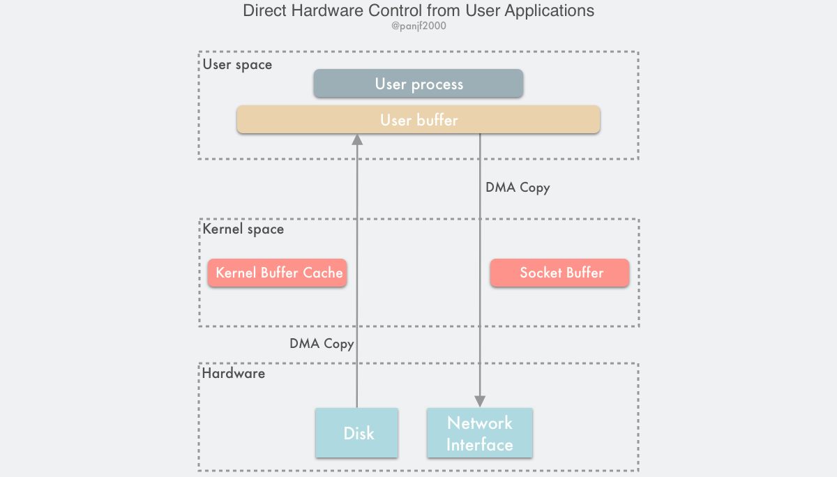
bypasses direct kernel I/O
As you can see, all the previous zero-copy methods are trying to optimize the reduction or removal of data copies between the user state and the kernel state and between the kernel state and the kernel state, and there are various ways to avoid these copies. So if we think about it differently: Isn’t the kernel the reason for all the effort to eliminate these copies? If we bypassed the kernel and did I/O directly, wouldn’t we have no more annoying copy problems? This is the Bypass Kernel Direct I/O technique.
This solution can be implemented in two ways.
- direct user access to the hardware
- kernel-controlled access to the hardware
Direct user access to hardware
This technique gives user processes direct access to hardware devices, which allows them to have direct access to read and write hardware devices, requiring only some virtual memory configuration-related work from the kernel during data transfer. This direct I/O without data copying and kernel intervention is theoretically the most efficient data transfer technique, but as mentioned earlier, there is no silver bullet that solves everything, and while this direct I/O technique is potentially very efficient, it is also very narrowly applicable and currently only works in limited scenarios such as MPI high performance communication, remote shared memory in cluster computing systems, etc.
This technique actually undermines one of the most important concepts of modern computer operating systems - hardware abstraction. As we mentioned before, abstraction is the most central design idea in computing, and it is thanks to abstraction and layering that the layers can focus on the real work without having to care about many of the underlying details, making the system work more efficiently and faster. In addition, NICs typically use less powerful CPUs, such as MIPS processors with simple instruction sets (without unnecessary features such as floating point calculations), and do not have much memory to accommodate complex software. As a result, only those dedicated protocols based on top of Ethernet, which are designed to be much simpler than TCP/IP and are mostly used in LAN environments where packet loss and corruption are rare and therefore complex packet acknowledgement and traffic control mechanisms are not necessary, will typically use this technology. Also, this technology requires custom NICs, so it is highly hardware dependent.
Compared with traditional communication designs, direct hardware access technology imposes various constraints on programming: Since data transfer between devices is done through DMA, the data buffer memory pages in user space must be page pinning to prevent their physical page frame addresses from being swapped to disk or moved to a new address, causing the DMA to copy the data. To avoid frequent page pinning system calls, the application must allocate and register a persistent memory pool for data buffering.
The technique of direct user access to the hardware allows for very high I/O performance, but its application areas and scenarios are extremely limited, such as node communication in clusters or networked storage systems. It requires custom hardware and specially designed applications, but accordingly requires relatively minor changes to the OS kernel and can be easily implemented as kernel modules or device drivers. Direct access to hardware can also pose serious security problems, as user processes have extremely high privileges to access the hardware directly, so if your programming is not well designed, you may consume already limited hardware resources or make illegal address accesses, and may also indirectly affect other applications that are using the same device as a result, and because it bypasses the kernel, you cannot have the kernel do it for you. control and management.
Kernel-controlled access to hardware
Kernel-controlled direct access to hardware is more secure than user-controlled direct access to hardware. It intervenes a bit more than the former in the data transfer process, but only as a proxy and does not participate in the actual data transfer process, as the kernel controls the DMA engine to do the buffer transfer for the user process. Again, this approach is highly hardware dependent, such as some NICs with integrated proprietary network stack protocols. One of the advantages of this technique is that the user-integrated I/O interface does not change, it is used like a normal read()/write() system call, all the dirty work is done in the kernel, and the user interface is very user-friendly. However, it should be noted that if something unpredictable happens during this technique that prevents the use of this technique for data transfer, the kernel will automatically switch to the most traditional I/O mode, i.e., the one with the worst performance.
This technique has the same problems as the direct user access hardware technique: during the DMA data transfer, the user process’s buffer memory page must be page pinning page locking and unlocked only after the data transfer is completed. multiple memory addresses stored in the CPU cache are also flushed to ensure data consistency before and after the DMA transfer. These mechanisms may lead to worse performance of the data transfer because the semantics of the read()/write() system calls do not notify the CPU in advance that the user buffer is going to participate in the DMA data transfer, and therefore cannot be loaded into the cache in advance to improve performance as the kernel buffer can. Since the user buffer memory pages can be located anywhere in physical memory, some poorly implemented DMA controller engines may have addressing limitations that prevent access to these memory areas. Some technologies, such as IOMMU in the AMD64 architecture, allow these limitations to be addressed by remapping the DMA address to a physical address in memory, but in turn may lead to portability issues since other processor architectures, even the Intel 64-bit x86 architecture variant EM64T, do not have such feature units. In addition, there may be other limitations, such as data alignment issues for DMA transfers, which in turn can lead to the inability to access arbitrary buffer memory addresses specified by the user process.
Transfer optimization between kernel buffers and user buffers
So far, we have discussed zero-copy techniques based on reducing or even avoiding CPU data copies between user space and kernel space. Although some techniques are very efficient, most of them have a narrow applicability, such as sendfile() and splice(), which are very efficient but are only applicable to scenarios where user processes do not need to process data directly, such as static file servers or proxy servers that forward data directly.
We now know that data can be transferred between hardware devices via DMA, but there is no such transfer mechanism that can be applied to data transfer between user buffers and kernel buffers. On the other hand, virtual memory mechanisms widely used in modern CPU architectures and operating systems have shown that it is possible to virtually copy and share memory between user processes and the kernel by remapping pages on different virtual addresses, albeit at a relatively large granularity of 4KB or 8KB per transfer.
Therefore, if data is to be processed within the user process (a scenario more common than direct forwarding) and then sent out, the transfer of data between user and kernel space is inevitable, and since it is unavoidable, optimization is the only option. Therefore, in this section we introduce two techniques for optimizing user- and kernel-space data transfers.
- dynamic remapping and copy-on-write (Copy-on-Write)
- Buffer Sharing
Dynamic Remapping and Copy-on-Write
Previously, we introduced the use of memory mapping techniques to reduce the copying of data between user space and kernel space. Usually, in simple mode, user processes read and write to shared buffers synchronously, so that there is no data race problem, but this mode is not very efficient, and one way to improve efficiency is to read and write to shared buffers asynchronously, and in this case, it is necessary to introduce protection mechanisms to avoid data conflicts. Copy on Write is one such technique.
Copy-on-write ( COW ) is an optimization strategy in the field of computer programming. The core idea is that if multiple callers request the same resource (e.g., memory or data storage on disk) at the same time, they will collectively obtain the same pointer to the same resource until one caller tries to modify the content of the resource, when the system actually copies a private copy to that caller, while the original resource seen by the other callers remains unchanged. remains unchanged. This process is transparent to all other callers. The main advantage of this approach is that if the caller does not modify the resource, no copy (private copy) is created, so multiple callers can share the same resource for read-only operations.
For example, after the introduction of COW technology, the user process reads the disk file for data processing and finally writes it to the NIC, first using memory mapping technology to make the user buffer and the kernel buffer share a section of memory address and mark it as read-only to avoid data copying, and when it is time to write the data to the NIC, the user process chooses the asynchronous write method, the system call will If the process tries to write to the shared buffer again, a COW event will be generated, allowing the process trying to write to the data to copy the data to its own buffer for modification. Here, only the memory page to be modified is copied, not all data is copied, and if other processes accessing the shared memory do not need to modify the data, no data copy is ever needed.
COW is a technology built on top of virtual memory flush mapping technology, so it requires hardware support from the MMU, which keeps track of which memory pages are currently marked as read-only. When a process tries to write to these pages, the MMU throws an exception to the operating system kernel, which handles the exception by allocating a copy of physical memory to the process and copying the data to this memory address, retransmitting the write operation to the MMU for the process to perform.
The biggest advantage of COW is that it saves memory and reduces data copying, but it does so at the cost of increasing the complexity of the OS kernel I/O process. When determining where to use COW to copy pages, it is important to note where free pages are allocated. Many operating systems provide a pool of free pages for such requests. These free pages are typically allocated when the process stack or heap is to be expanded or when there are write-time copy pages to be managed. Operating systems typically allocate these pages using a technique called Zero Filling on Demand. Zero-fill-on-demand pages are zero-filled before they need to be allocated, so the old contents are cleared.
Limitations:
The zero-copy technique of COW is more suitable for scenarios where more reads and fewer writes result in fewer COW events, because the system overhead from COW events is much higher than that from a single CPU copy. In addition, in practice, to avoid frequent memory mapping, the same memory buffer can be used repeatedly, so you do not need to unmap the memory page after using the shared buffer only once, but recycle it repeatedly to improve the performance, but this persistence of memory page mapping does not reduce the system overhead due to page table round-trip movement and TLB flushing. The read-only flag of the page is changed to write-only each time the page is locked or unlocked after receiving a COW event.
Buffer Sharing
As you can see from the previous introduction, the traditional Linux I/O interface is based on copy/copy: data needs to be copied between the OS kernel space and the user space buffers. When using the read() system call, the kernel copies the data read from memory or a device such as a NIC (Network Interface Controller) into this user buffer, while when using the write() system call, the data from the user memory buffer is copied to the kernel buffer.
In order to implement this traditional I/O model, Linux has to perform memory virtual mapping and unmapping at every I/O operation. The efficiency of this memory page remapping mechanism is severely limited by the cache architecture, MMU address translation speed, and TLB hit rate. If the overhead of virtual address translation and TLB flushing for handling I/O requests can be avoided, it is possible to greatly improve I/O performance. Buffer sharing is one of the techniques used to solve these problems.
The first operating system to support Buffer Sharing was Solaris, and later, Linux gradually supported it, but it is still incomplete and immature today.
OS kernel developers have implemented a buffer sharing framework called fbufs, or Fast Buffers, which uses a fbuf buffer as the smallest unit of data transfer. fbufs allocates a buffer pool for each user process, which stores pre-allocated (or reallocated when used) buffers that are mapped to both user and kernel memory space. fbufs creates buffers in a single virtual memory mapping operation, effectively eliminating most of the performance loss caused by storage consistency maintenance. maintenance, effectively eliminating most of the performance loss caused by storage consistency.
The traditional Linux I/O interface is accomplished by copying data between the user buffer and the kernel buffer, which requires a large number of data copies. These operations can lead to performance loss. If the fbufs framework is used for data transfer, the buffers can be cached in the pool for recycling instead of reallocating them every time. From the level of sending and receiving data, user processes and I/O subsystems such as device drivers and NIC (Network Interface Controller) can directly transfer the entire buffer itself instead of its data content, which can also be interpreted as transferring the memory address pointer, thus avoiding a large number of data content copies: user processes/IO subsystems write data to the kernel by sending one fbuf after another instead of directly passing the data content. In contrast, the user process/IO subsystem reads data from the kernel by receiving one fbuf after another, thus reducing the data copy overhead of the traditional read()/write() system calls.
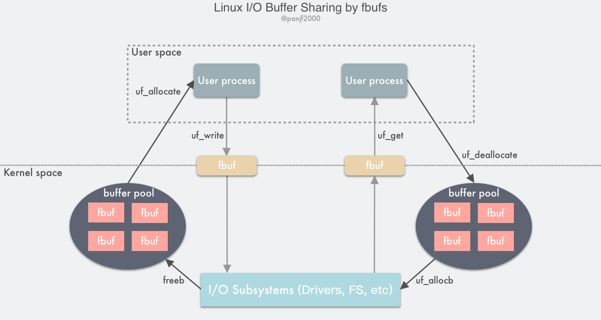
- The sender user process calls
uf_allocateto get a fbuf buffer from its own buffer pool, fills it with the contents, and then callsuf_writeto send a file descriptor pointing to the fbuf to the kernel. - After receiving the fbuf, the I/O subsystem calls
uf_allocbto get a fubf from the buffer pool of the receiving user process and fill it with the received data, then sends a file descriptor to the user area pointing to the fbuf - The receiving user process calls
uf_getto receive the fbuf, reads the data for processing, and callsuf_deallocateto put the fbuf back into its own buffer pool when it is finished
Flaws of fbufs:
The implementation of shared buffer technology relies on the user process, the OS kernel, and the I/O subsystem (device drivers, file system, etc.) working together. For example, a poorly designed user process can easily contaminate the data by modifying the fbuf that has been sent out, and worse, this problem is hard to debug. Although the design of this technology is very exciting, its threshold and limitations are no less than those of the other technologies introduced earlier: first, it will cause changes to the operating system API, requiring the use of some new API calls, second, it will require device drivers to cooperate with the changes, and because it is a memory share, the kernel needs to carefully implement a mechanism to protect and synchronize the data in this shared memory, and This concurrent synchronization mechanism is very prone to bugs and thus increases the complexity of the kernel code, and so on. Therefore, this type of technology is far from being mature and widely used, and most implementations are still in the experimental stage.
Summary
In this article, I have mainly explained the underlying principles of Linux I/O, then introduced and analyzed Zero-copy technologies in Linux, and given ideas for optimizing and improving the I/O module in Linux.
The Zero-copy techniques in Linux can be grouped into the following three categories.
- Reduce or even avoid data copying between user space and kernel space: In some scenarios where the user process does not need to access and process the data during data transfer, data transfer between Linux’s
Page Cacheand the user process’s buffer can be completely avoided, allowing data copying to be done entirely in the kernel, or even more subtly by Even more clever ways to avoid data copying in the kernel are possible. This is usually done by adding new system calls, such as mmap(), sendfile(), and splice() in Linux. - Direct I/O bypassing the kernel: Allows user-state processes to transfer data directly to the hardware, bypassing the kernel, with the kernel only taking care of administrative and auxiliary tasks during the transfer. This approach is actually somewhat similar to the first one, which also tries to avoid data transfer between user space and kernel space, except that the first approach puts the data transfer process in the kernel state, while this approach directly bypasses the kernel and hardware communication, with similar effects but completely different principles.
- Transfer optimization between kernel buffers and user buffers: This approach focuses on optimizing the CPU copy between the user process buffers and the OS page cache. This approach continues the traditional way of communication, but is more flexible.
This article provides a comprehensive and detailed analysis of the underlying principles of Linux I/O from virtual memory, I/O buffers, user state & kernel state, and I/O modes, and analyzes the disadvantages of the traditional I/O mode of Linux. By distinguishing and comparing the zero-copy technology and the traditional I/O mode, the reader is taken through the evolution of Linux I/O. By helping the reader understand the optimization and improvement ideas of the Linux kernel for I/O modules, it is believed that the reader will not only understand the design principles of the Linux underlying system, but also be inspired in the process of optimizing and improving their own program design in the future.