At the Google I/O 2022 conference, Google Cloud released AlloyDB, a cloud-native database compatible with PostgreSQL standard, which claims to be twice as fast as its Amazon counterpart (Aurora?). This slogan should not be enough for old users to migrate, but for new users, it does have some appeal.
Since I mainly do storage, here’s a breakdown of AlloyDB storage based on this Google article introducing the AlloyDB storage layer blog post, I will analyze the AlloyDB storage architecture and see what the highlights of its design are.
Overall Architecture
In general, AlloyDB is divided into Database layer and Storage layer. Among them, DB layer is used to be compatible with PostgreSQL protocol, parsing SQL statements and converting them into read/write requests to send to storage layer. For the storage layer, it can be subdivided into three layers.
-
log storage layer: The DB layer converts writes into operation logs, or WALs, and writes them to the storage layer. log storage is responsible for efficient writing and storage of these log records.
-
LPS Layer: The Log Processing Service (LPS) layer consumes the WALs from the log storage layer and generates blocks, which is essentially a Materialized process.
-
block storage layer: The block layer corresponding to standalone PostgreSQL, used to serve queries, providing parallelism through sharding and fault tolerance across zones through replication.
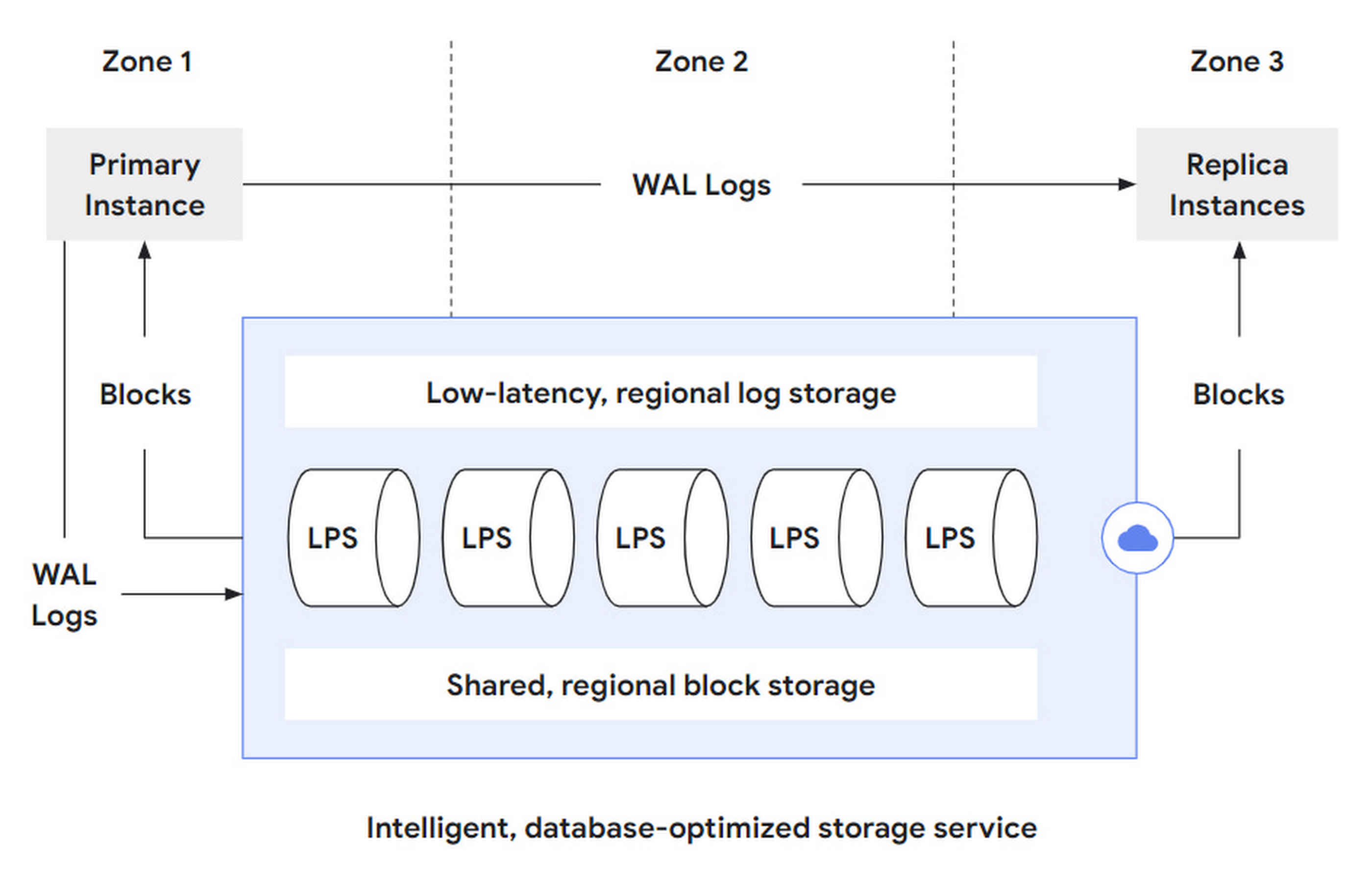
That is, AlloyDB further splits its storage layer into two storage layers and one compute layer to disentangle the complexity of.
- log storage layer, which takes over the write requests from the DB layer. But it only supports append only writes, so it can achieve low latency and high availability, and can use LSN to do read/write concurrency control and distributed transactions.
- The block storage layer takes over the query requests from the DB layer. Although not mentioned in the text, but blindly guess that the block provided only supports single write multiple reads (write once then becomes immutable), in order to facilitate caching and version control.
- The LPS layer, the data mover between the two sub-storage layers, is responsible for both block generation and reading, stateless and scalable. Instances can be dynamically added or deleted to keep track of changing load based on various signals such as load and statistical information.
The storage layer is essentially to provide block read and write services, AlloyDB split out the log storage layer for writing and the block storage layer for reading. Materializing the storage tier based on log services is a classic (or even old) architecture in the field of distributed databases, but how to combine them efficiently is still a test of engineering skills.
Another advantage of log service-based materialization is that the same data can be materialized in different ways to support different workloads, such as materializing data on demand into data formats optimized for TP and AP, i.e., supporting HTAP.
Read and Write Flow
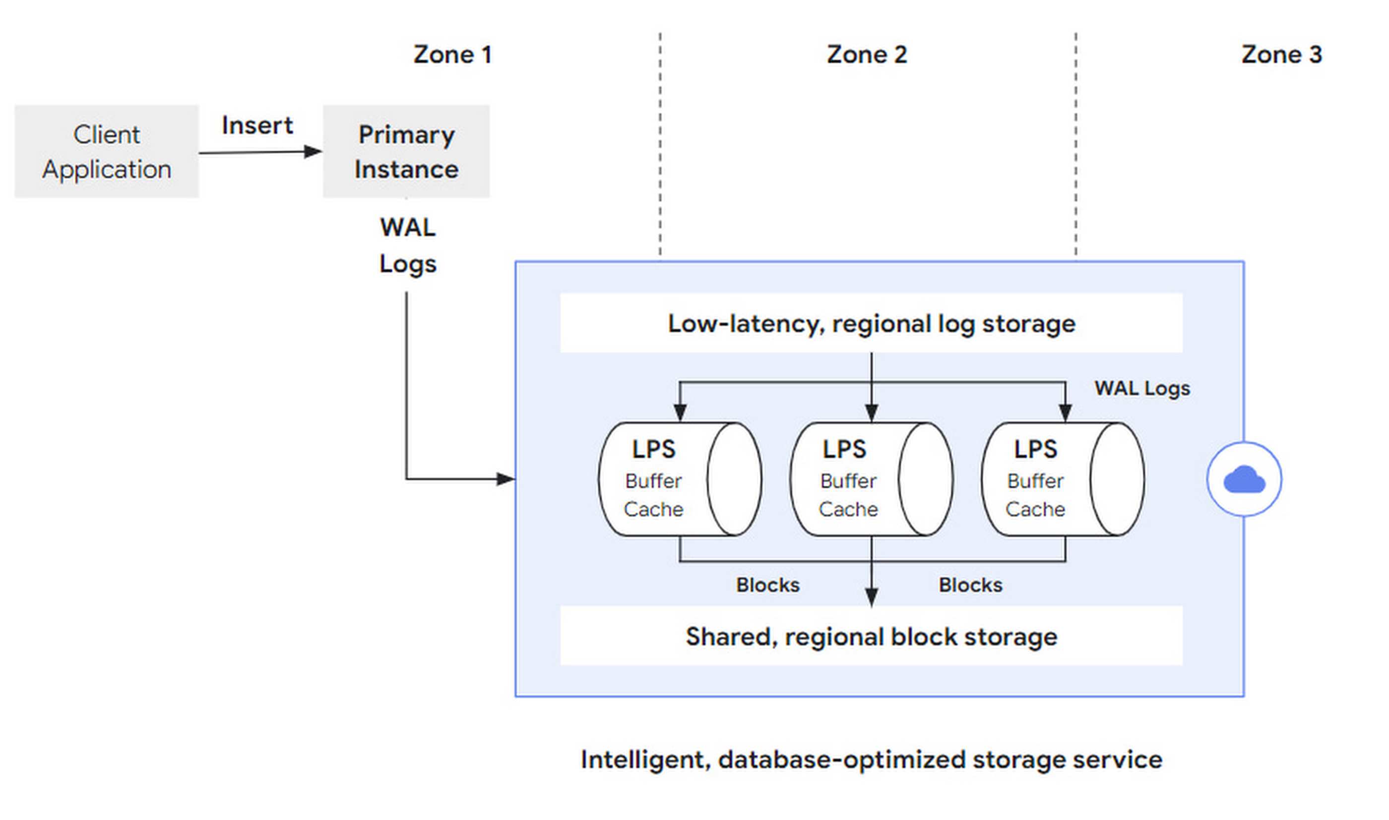
A write request (e.g. SQL insert), initiated by the client to the primary instance, is parsed by the DB layer and sent to the storage layer as a set of WAL Records. After a successful WAL synchronous write, the transaction commit is successfully returned. After that, LPS materializes the logs asynchronously as Blocks.
The original article did not expand on this, but how to segment and fault-tolerant the logs, how to deploy them in multiple locations, and how to manage the log lifecycle are also critical design points.
A read request (e.g. SQL query), initiated by the client to any instance, is parsed at the DB layer and returned directly if it hits the cache (Buffer Cache) in that DB layer; if there is not enough data cache for the request, it can go to a larger, second-level cache-like Ultra-fast Cache to retrieve it, and if it hits, it can still can still not access the storage layer.
If the Ultra-fast Cache is still missing the required block, a block read request is sent to the storage layer with block id and LSN.
- block id is used to retrieve the block.
- LSN is used to wait for LPS apply progress to ensure consistency view.
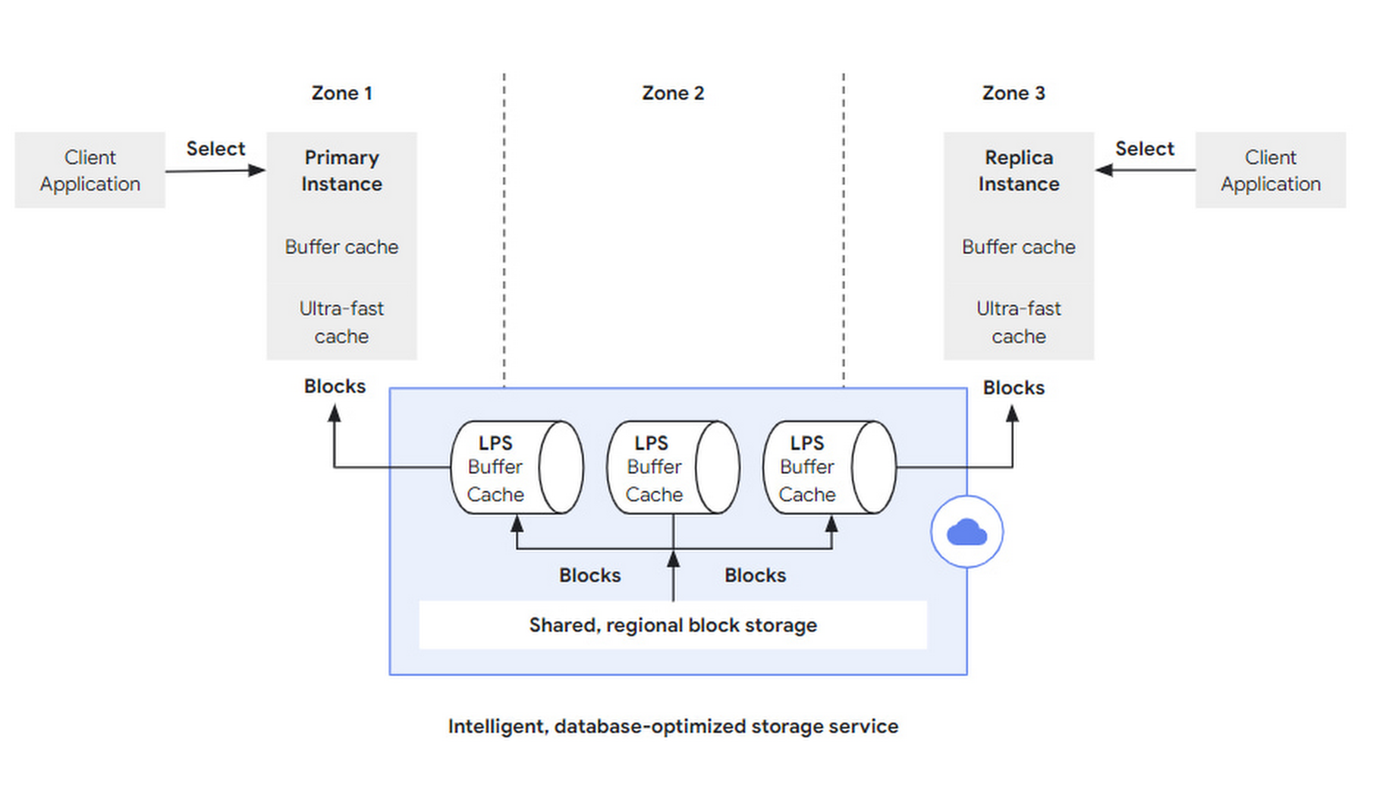
In the storage layer, LPSs are responsible for block reads and writes, and each LPS maintains a Buffer Cache, which is an interesting term.
- Buffer, which is generally used when writing to improve write throughput by combining multiple writes into one block.
- Cache, generally used for reads, bridges the access speeds of different media to reduce latency.
Here, the two are combined into one, LPS first writes to its own Buffer Cache during log replay (log apply), at which time the Buffer Cache acts as a buffer to be flushed to the block storage in bulk; LPS receives a Buffer Cache before it flushes the Buffer Cache to the block storage, if it receives a If LPS receives a block read request and hits the Buffer Cache before it flushes the Buffer Cache to the block storage, it can return directly, and then the Buffer Cache acts as the cache.
Of course, LPS needs to maintain a data structure like a dirty table for Buffer Cache to track the life cycle of each block and the expiration time of the next swipe.
Resilient Scaling
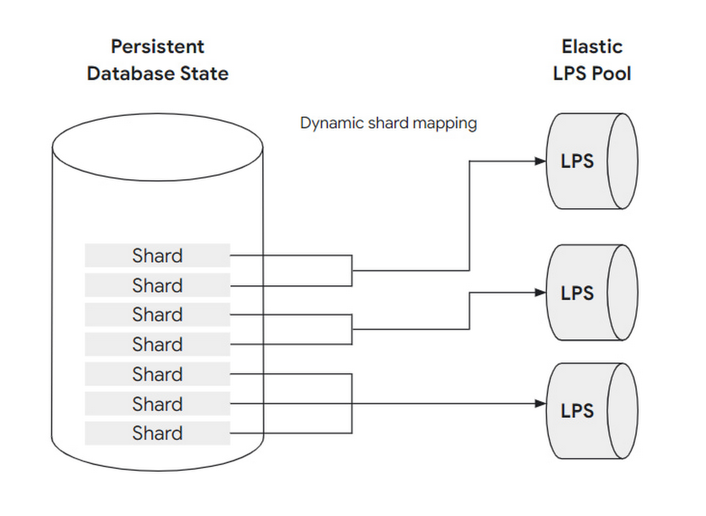
To cope with changing loads, the number of LPS instances is designed to be scalable: that is, to adjust the mapping relationship between LPS and block shard. Before further explaining how to scale, let’s sort out the concept of block, shard and LPS instances and the relationship.
A set of blocks is assembled into a shard, and a shard is handled by at most one LPS instance, but an LPS instance can handle multiple shards at the same time.
By analogy with a restaurant, a block can be understood as a guest, a shard as a table, and an LPS instance as a waiter:
- when the load is low, only one server is needed to take care of all the guests at the tables in the restaurant.
- when the load is very high, up to one waiter can be assigned to each table.
This dynamic adjustment can be fully automated without user perception or intervention. And because LPS has no state (Buffer Cache does not count as state, think why), it can quickly scale.
Zones
To tolerate zone failures, AlloyDB puts multiple copies of each block slice into different zones.
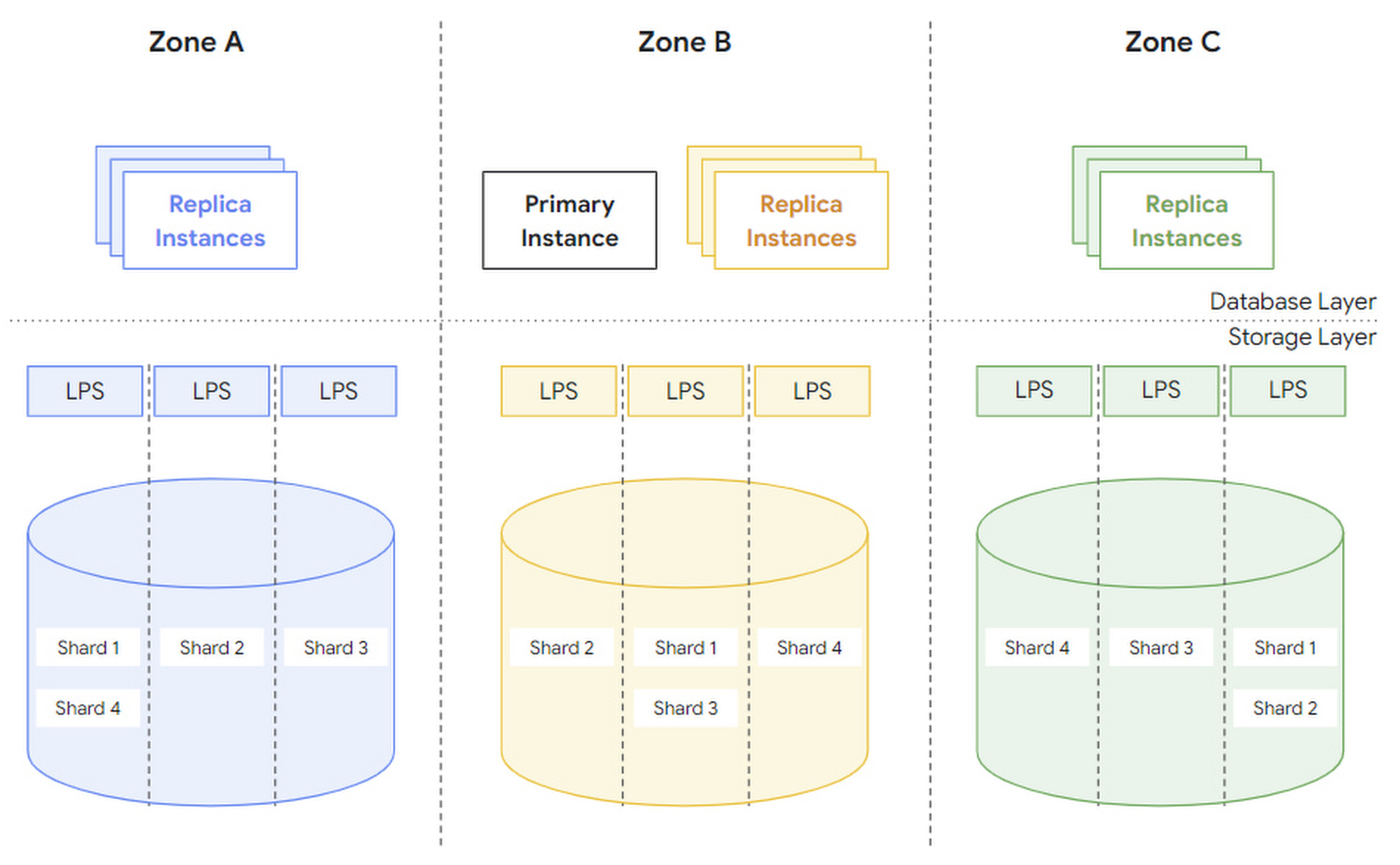
There are two concepts mentioned in the article, region and zone, which I did not verify, but I guess region refers to physical region and zone refers to logical region. When a zone fails, a new zone is pulled up in the same region and the data is recovered:
- first use a snapshot of another copy to recover.
- then play back the WAL after that snapshot.
Under normal circumstances, each zone can be served independently, and there is no particular amount of cross-zone traffic.
In addition, AlloyDB also supports logical (e.g. a database) manual and automatic backups to prevent users from accidentally deleting data.
Summary
AlloyDB’s storage layer is implemented based on log service, with two layers of storage log storage, block storage and one layer of compute LFS. based on LSN to control concurrency and dynamically scale LFS to cope with the load.