This article introduces the service discovery and traffic exposure mechanism in K8S clusters, including the workload type, service type, DNS resolution principle, and the rules of Layer 4 service exposure and Layer 7 service exposure in K8S.
1. Cloud-native foundation concepts
1.1 K8S Architecture
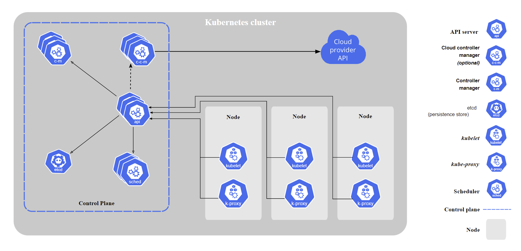
The following diagram is a brief introduction to the K8S architecture design in the official K8S documentation. This architecture diagram focuses on the relationship between the cloud vendor’s API, the control plane (Control Plane) and the working nodes (Node) in the K8S cluster from the cloud vendor’s perspective, but strips out the third-party implementations such as CRI, CNI, CSI, etc.
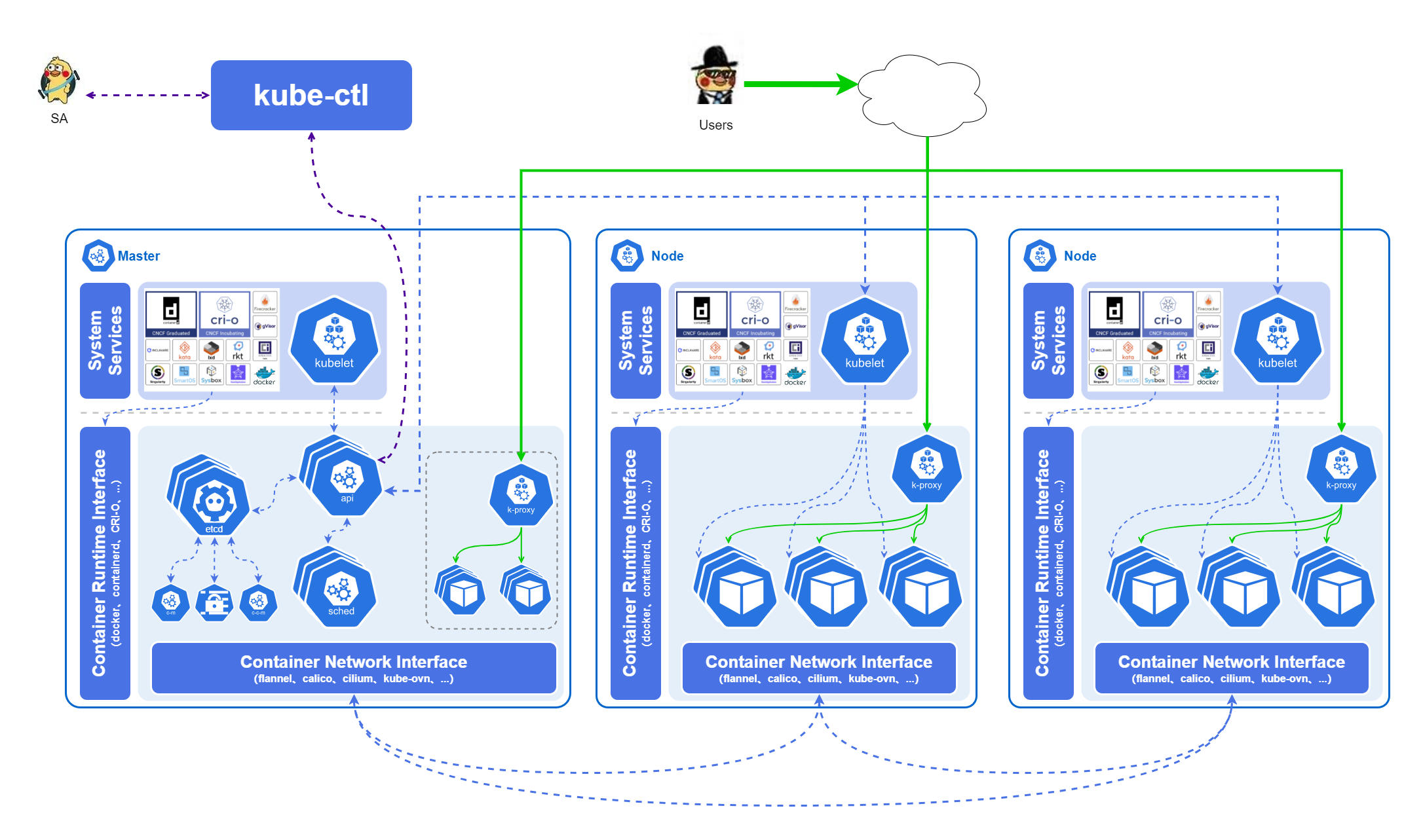
Based on the official architecture diagram we introduce CRI and CNI into the architecture diagram, we can get this model as follows.
kube-apiserverexposes the Kubernetes API to the public. it is the Kubernetes front-end control layer. It is designed to scale horizontally, i.e. by deploying more instances.etcdis used for Kubernetes back-end storage. etcd is responsible for keeping configuration information of Kubernetes Cluster and status information of various resources, always providing a backup plan for etcd data of Kubernetes cluster. When data changes, etcd quickly notifies Kubernetes-related components.- When there is a new Pod in the cluster that has not yet been assigned to a Node,
kube-schedulerwill analyze and assign it to the most appropriate Node based on the load on each Node and the application’s needs for high availability, performance, data affinity, and other aspects. to the most appropriate node. kube-controller-managerruns the controllers, which are background threads that handle regular tasks in the cluster. Logically, each controller is a separate process, but to reduce complexity, they are compiled into separate executables and run in a single process. These controllers include: Node Controllers (Node Controllers), Replication Controllers (Replication Controllers), Endpoint Controllers (Endpoints Controllers), Service Account & Token Controllers`), etc.kube-proxyis a network proxy that runs on each node in the cluster. kube-proxy implements the Kubernetes service abstraction by maintaining network rules on the host and performing connection forwarding. service logically represents multiple Pods on the backend, and the outside world accesses the Pods through service. The requests received by service are forwarded to Pods through kube-proxy. kube-proxy service is responsible for forwarding TCP/UDP data streams from service to back-end containers. If there are multiple replicas, kube-proxy will implement load balancing.- The three major plug-ins of K8S control Runtime, Network and Storage respectively, namely
Container Runtime Interface (CRI),Container Network Interface (CNI)andContainer-Storage-Interface (CSI). Note that CRI and CNI are the base components that every K8S cluster must deploy, while CSI is not necessarily needed, and is generally only needed when we need to run stateful services.
1.2 CNI Foundation
K8S itself does not implement the network model within the cluster, but provides a CNI interface for third parties to implement by abstracting it out, which saves development resources to focus on K8S itself, and can leverage the power of the open source community to create a rich ecology, some implementation details and requirements of CNI we can find on github, so we won’t go into the details here.
Focusing on the K8S definition of the network model within a cluster.
- Any two PODs in a K8S cluster can communicate directly and do not need to perform NAT
- Each Pod in a K8S cluster must have its own unique, independent and accessible IP (IP-per-Pod)
K8S does not care about how each CNI specifically implements the above ground rules, as long as the final network model conforms to the standard. So we can ensure that no matter what CNI is used, the Pod network within a K8S cluster is a huge flat network, and each Pod has equal status in this network. This design brings great convenience to many scenarios such as service discovery, load balancing, service migration, application configuration within the cluster.
1.3 Overlay networks
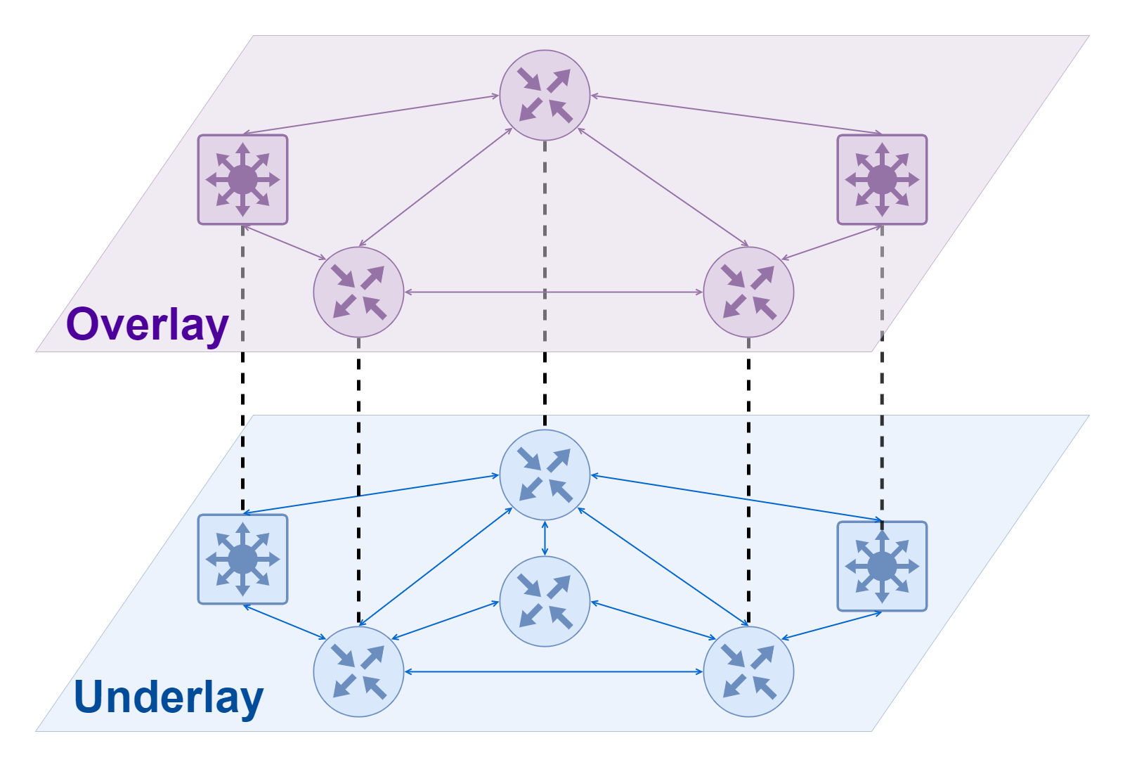
An overlay network can be understood as a virtual network built on top of another network, a concept that is often seen in SDNs. Similar to virtual NICs that need to rely on physical NICs to communicate, Overlay networks cannot just appear out of thin air and need to rely on an underlying network often referred to as an Underlay network. The Underlay network is an infrastructure layer dedicated to carrying user IP traffic, and the relationship between it and the Overlay network is somewhat similar to that of a physical machine and a virtual machine; both the Underlay network and the physical machine are real entities that correspond to real network devices and computing devices, respectively. Overlay networks and virtual machines are virtualized layers that depend on the lower layer entities using software.
In a K8S cluster that uses Overlay network, we can think of the Underlay network at the bottom as the network where the Node nodes of the K8S cluster are located, while the Overlay network at the top is generally used to handle the network communication between Pods . Under normal circumstances, the Underlay network and the Overlay network do not interfere with each other, and they do not know each other’s network situation. However, since the Overlay network needs to rely on the Underlay network to transmit data, when the data from the Overlay network is sent to the Underlay network for transmission, it needs to encapsulate the packets and turn them into packets that the Underlay network can understand; conversely, when the data is transmitted from the Underlay network back to the When the data is transmitted from the Underlay network back to the Overlay network, it needs to be unpacked. The two common network protocols used for encapsulation in the K8S Overlay network implementation are VXLAN and IP-in-IP.
The main advantages of using Overlay network are as follows.
- Highly flexible, Overlay network is separated from the underlying hardware network facilities, so it has advantages that traditional Underlay network cannot match in scenarios such as cross-room and cross-data center
The main disadvantages of using Overlay networks are as follows.
- Slight performance impact. The process of encapsulating packets takes up a small amount of CPU, and the extra bytes needed to encode the encapsulation (VXLAN or IP-in-IP header) in the packet reduces the maximum size of internal packets that can be sent, which in turn can mean more packets need to be sent for the same amount of total data.
- Pod IP addresses cannot be routed outside the cluster.
1.4 Border Gateway Protocol (BGP)
BGP (Border Gateway Protocol/Border Gateway Protocol) is a standards-based network protocol for sharing routes across a network. It is one of the fundamental components of the Internet and has excellent scaling characteristics. In K8S, BGP is a routing protocol with a high presence, and there are many related CNI or LoadBalancer that use BGP protocol to implement features such as route reachability or ECMP.
The best supported and most widely used CNI for BGP protocol is Calico, and Cilium also has support for BGP mode which is still in beta stage.
1.5 Routability (routability)
An important difference between different K8S cluster networks is the routability of the Pod’s IP outside the K8S cluster.
Since Pods within a K8S cluster are necessarily routable to each other, the routability between services outside the cluster to Pods within the cluster is explored here.
Routing Unreachable
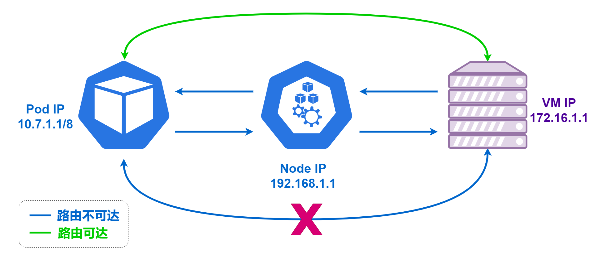
The so-called routing unreachable means that there is no way for machines outside the K8S cluster to establish a direct connection with the Pods inside the cluster, and the servers outside the cluster do not know how to route packets to the Pod IPs.
In this case, when a Pod within the cluster needs to actively establish a connection with a service outside the cluster, it will perform SNAT (Source Network Address Translation) through K8S. In this case, the IP of the server outside the cluster is the Node IP of the K8S cluster node where the Pod is located instead of the Pod’s own IP, and the destination IP of the returned data sent by the server outside the cluster is always the Node IP of the K8S cluster node, and the data is sent back to the Pod after the Node IP has been translated. In this case, servers outside the cluster cannot know the IP of the Pod, and cannot directly obtain the real request IP.
Conversely, it is more complicated because servers outside the cluster do not know how to route packets to Pod IPs, so there is no way to actively request these Pods, and they can only expose services outside the cluster through K8S services (NodePort, LoadBalancer, Ingress). At this point, the server outside the cluster is accessing a K8S service, not a specific Pod.
Reachable by route
If the Pod IP address is routable outside the cluster, the pod can connect directly to servers outside the cluster without SNAT, and servers outside the cluster can connect directly to the pod without going through the K8S services (NodePort, LoadBalancer, Ingress).
The advantages of a Pod IP address that can be routed outside the cluster are as follows.
- Reduced network hierarchy, reduced network-level architectural complexity, reduced user understanding costs, maintenance costs, Debug costs, etc.
- Simpler implementation in this architecture for special application scenarios (e.g., machines outside the cluster need to connect directly to Pods)
The main disadvantages of Pod IP addresses that can be routed outside the cluster are as follows.
- Pod IPs must also be unique in the network outside the cluster. If there are multiple K8S clusters that need to be routed outside the cluster, then a different CIDR needs to be used for each cluster Pod. this requires some planning for internal IP usage and the possibility of running out of internal IPs when the cluster is large enough.
Determinants of routability
- If the cluster is using an overlay network, in general Pod IPs cannot be routed outside the cluster
- If no overlay network is used, it depends on the deployment environment (cloud vendor/local deployment), the CNI used (Calico-BGP, Cilium-BGP, etc.), and the actual network planning, etc.
- Current implementation of out-of-cluster routability for K8S networks is generally through BGP protocol
2. K8S Service Exposure
Under normal circumstances, the workloads we deploy in a K8S cluster are required to provide services externally. The “external “ here refers to providing services to all external servers other than this load, and depending on whether these external servers are located in the K8S cluster, we can divide them into K8S cluster internal traffic and K8S cluster external traffic.
2.1 Workload and SVC
Before we start, let’s clarify a few points.
- Workload (Workload) in K8S generally refers to real work tasks in a cluster. For example,
deploymentsfor stateless services,statefulsetsfor stateful services,daemonsetsfor some special purposes,cronjobsfor timed services, etc., all these belong to the workload in K8S. - The service (SVC) in K8S is more like a collection of rules, where all the pods that meet certain conditions are grouped into a Service, and then a specific Service is formed.
- Each SVC in K8S will have a corresponding domain name, which is composed in the format of
$service_name.$namespace_name.svc.$cluster_name. Generally speaking,$cluster_namein a k8s cluster iscluster.local, and this field is generally This field is usually set when the cluster is created, and it can be very troublesome to change it later.
In summary, we can conclude the following.
- the workload (workload) and service exposure (service) in K8S are isolated from each other and given to different
apis to implement - each SVC will have a
service name+namespace+svc+cluster name/$service_name.$namespace_name.svc.$cluster_namedomain name that can be used for access (e.g.app.namespace.svc.cluster.local) - Access between services within a K8S cluster is mainly through this domain name
2.2 Types of SVCs
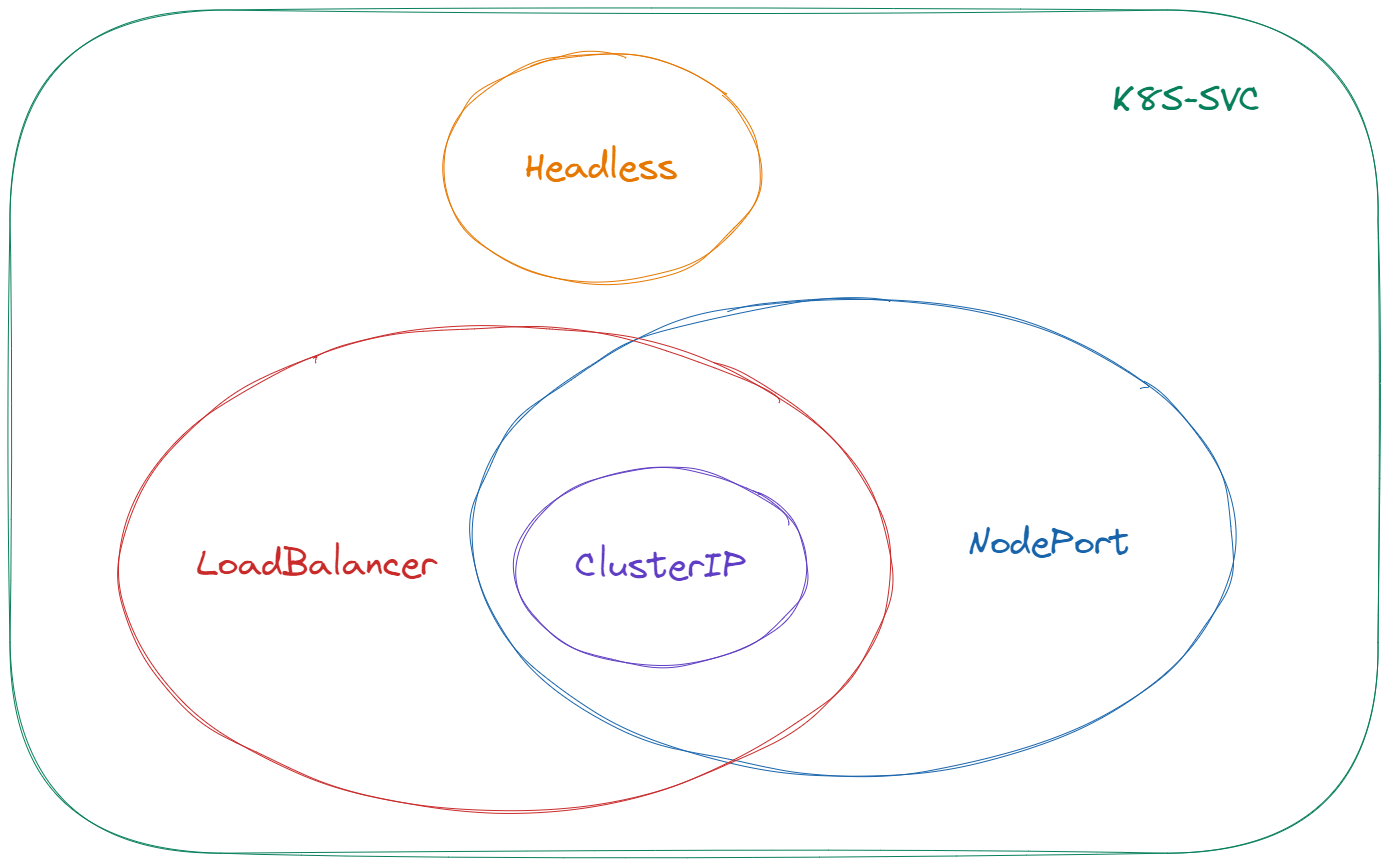
Generally speaking svc can be divided into four categories: Headless, ClusterIP, NodePort, LoadBalancer. The relationship between the four is not completely mutually exclusive, as follows.
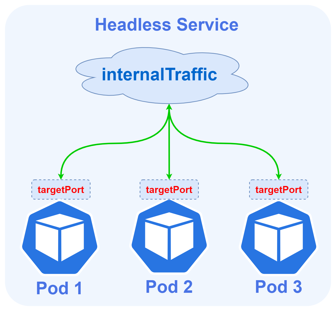
Headless Services
- The
Headlesstype service is completely mutually exclusive with the other three, and theHeadlessService can be created by specifying the Cluster IP (spec.clusterIP) with a value of"None". - At this point the result of the domain name resolution of this service is all the Pod IPs associated with this service, and the requests will reach the pods directly when accessed using this domain name.
- The load balancing policy at this point is equivalent to using only DNS resolution for load balancing, and not using k8s built-in kube-proxy for load balancing.
- the
Headlesstype service does not create SRV records belonging to the corresponding domain name.
Headless Services The advantage of this approach is that it is simple enough and the request link is short, but the disadvantage is also obvious, that is, the DNS caching problem brings uncontrollable. Many programs query DNS and do not refer to the standard TTL value, either frequent queries put enormous pressure on the DNS server, or the query is cached all the time after the service has changed and is still requesting the old IP.
ClusterIP Services
In a Kubernetes cluster, each Node runs a kube-proxy process. The kube-proxy is responsible for implementing a form of VIP (Virtual IP) for the Service, commonly referred to as ClusterIP Services.
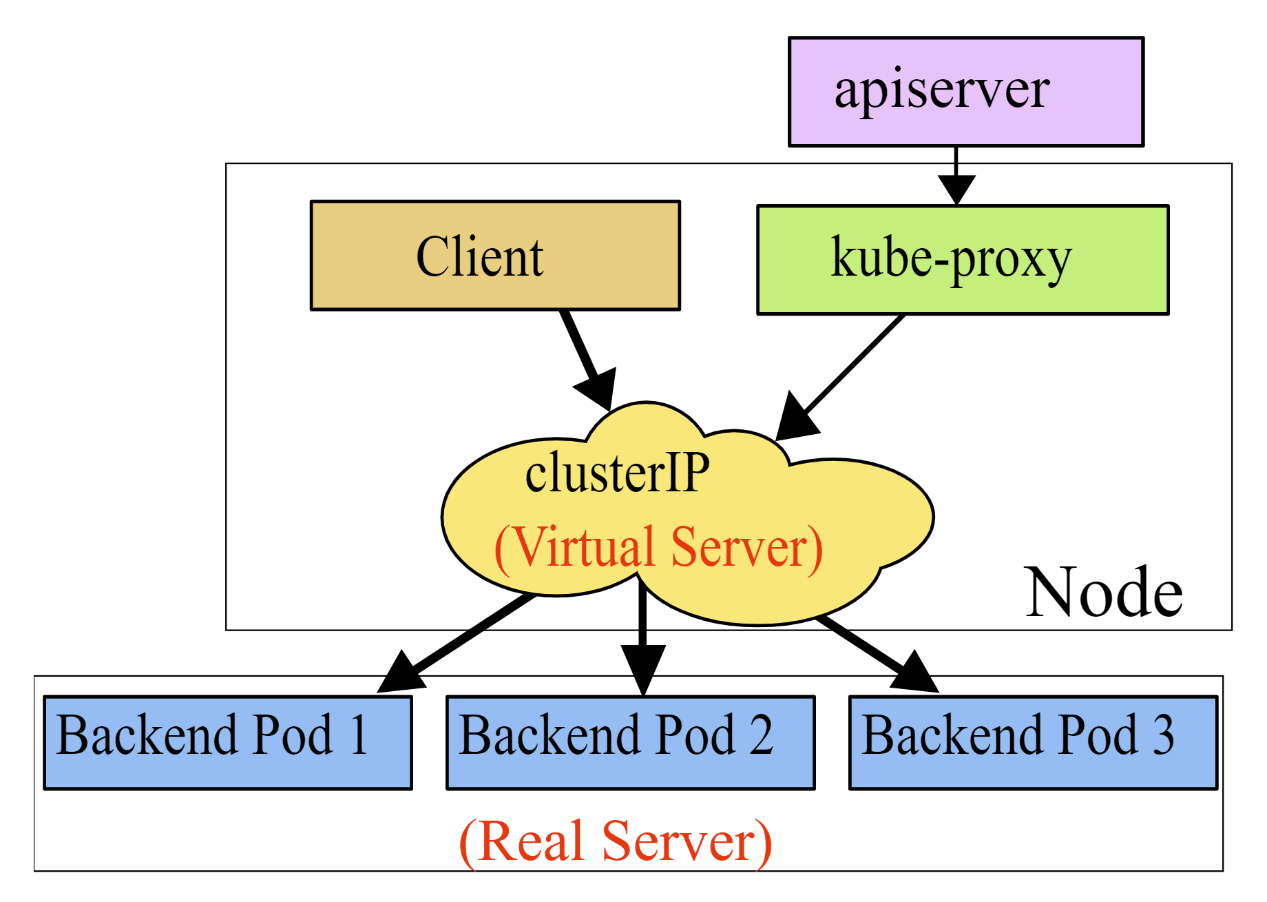
ClusterIPis the most commonly used service type and the default service type, as well as the basis for the two servicesNodePort,LoadBalancer.- For services of type
ClusterIP, K8S assigns a VIP calledCLUSTER-IPto the service. - ClusterIP is a separate IP segment, distinct from the K8S host node IP segment and Pod IP segment, also defined at cluster initialization time.
- ClusterIP can be seen inside the
kube-ipvs0NIC on top of each k8s host node. - The result of domain name resolution for services of the ClusterIP type is this VIP, and requests will first go through the VIP and then be distributed by the kube-proxy to the individual pods.
- If k8s uses ipvs, you can use the ipvsadm command on top of the K8S host node to see the forwarding rules for these load balancing.
- The
ClusterIPtype service also creates the SRV record corresponding to the domain name it belongs to, and the port in the SRV record is the port of the ClusterIP
The advantage of ClusterIP Services is that the VIP is located in front of the Pod, which can effectively avoid the problems caused by direct DNS resolution mentioned earlier; the disadvantage is also obvious, when the volume of requests is large, the processing performance of the kube-proxy component will first become the bottleneck of the entire request link.
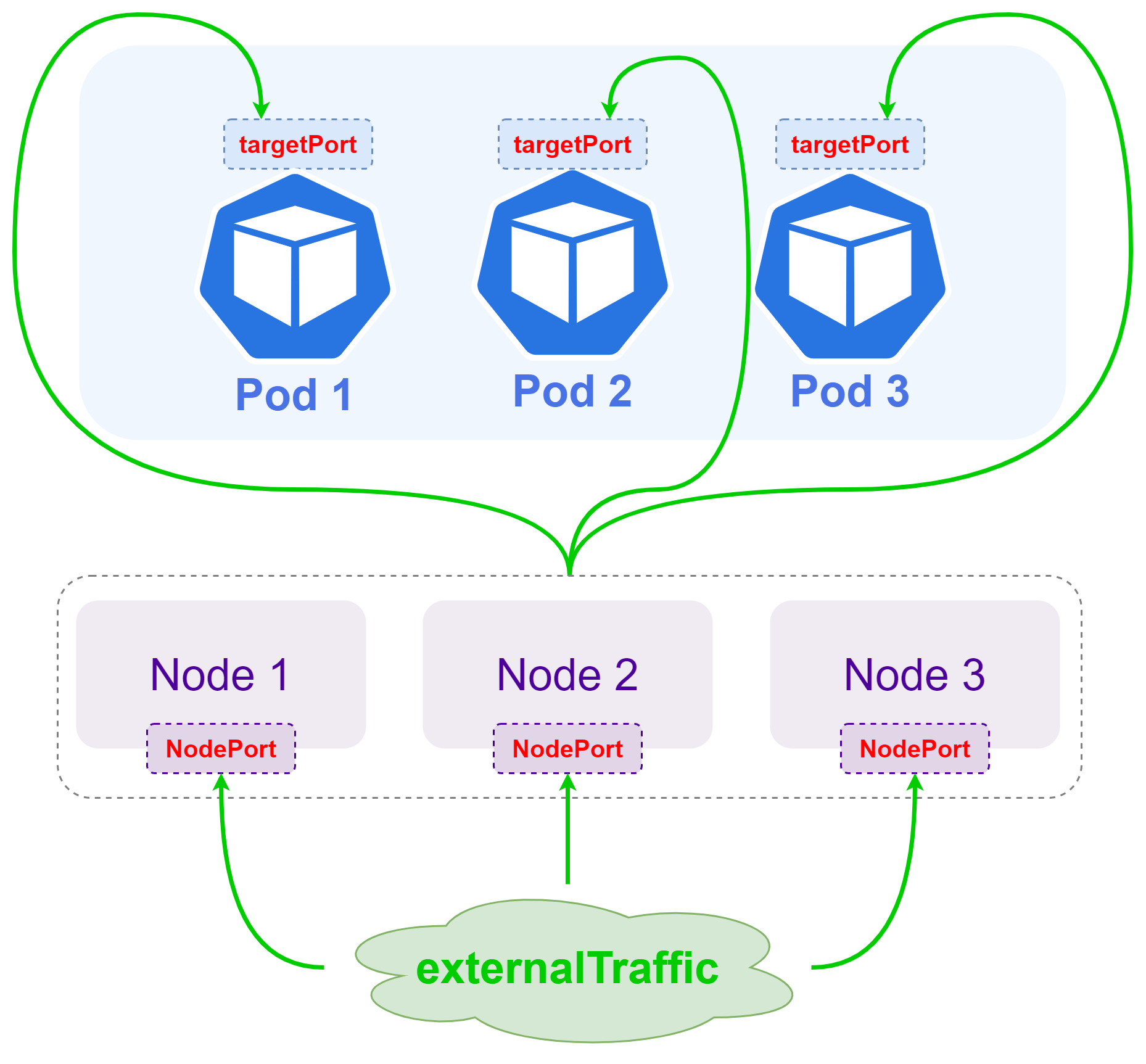
NodePort Service
- Starting with NodePort, the service is not limited to be exposed inside the K8S cluster, but can be provided outside the cluster
- The NodePort type picks a port on top of the K8S host node to assign to a service (default range is 30000-32767), and users can access the service by requesting the specified port from any K8S node IP
- NodePort Service domain name resolution results in a
CLUSTER-IP, the load balancing logic and implementation of requests within the cluster is the same asClusterIP Service. - The request path of the NodePort service is directly from the K8S node IP to the Pod and does not go through the ClusterIP, but the forwarding logic is still implemented by
kube-proxy.
The advantage of the NodePort Service approach is that it is very simple to expose the service to the outside of the cluster through K8S’s own functionality; the disadvantages are obvious: the port limitations of NodePort itself (limited number and range of options) and the performance bottleneck of the kube-proxy component when the volume of requests is high.
LoadBalancer Service
- LoadBalancer service type is the most advanced and elegant way for K8S to expose services outside the cluster, and also the highest threshold.
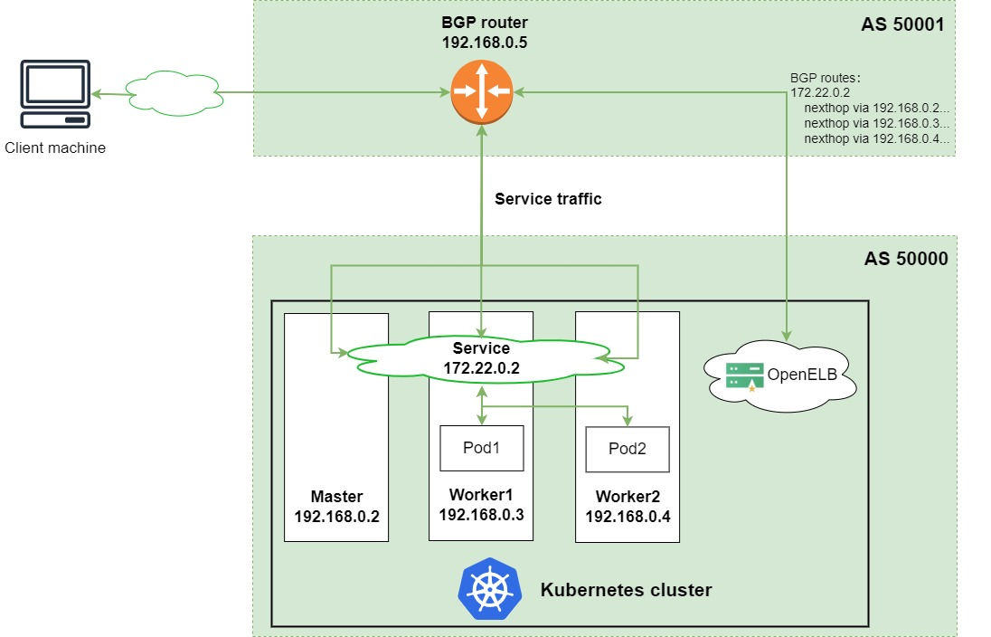
- LoadBalancer service type requires the K8S cluster to support a cloud-native LoadBalancer, which is partly not implemented by K8S itself but given to the cloud vendor/third party, so for cloud environments K8S clusters can directly use the LoadBalancer provided by the cloud vendor, and of course there are some open source cloud-native LoadBalancer, such as MetalLB, OpenELB, PureLB, etc..
- The resolution result of the LoadBalancer service domain name resolution is a
CLUSTER-IP. - The LoadBalancer service also assigns an
EXTERNAL-IP, through which machines outside the cluster can access the service. - LoadBalancer service will create NodePort at the same time by default, which means a LoadBalancer type service is also a NodePort service and also a clusterIP service; some cloud-native LoadBalancer can create a NodePort service by specifying
allocateLoadBalancerNodePorts: falseto deny the creation of NodePort services.
We still borrow the diagram from OpenELB’s official website to explain the process, and note that this is BGP mode.
The advantage of LoadBalancer Service is that it is convenient, efficient, and applicable to a wide range of scenarios, and can cover almost all external service exposures; the disadvantage is that there are few choices of mature and available cloud-native LoadBalancer, and the implementation threshold is high.
2.3 Identifying Port Concepts
When we do SVC and Workload deployment configuration, we often encounter various configuration items with Port in their names, which is one of the several concepts in K8S that are easy to confuse people. The relationship between the four can be more clearly distinguished by the following diagram.

nodePort: works only for the Loadbalancer service and the NodePort service, which is used to specify the port of the host node of the K8S cluster, the default range is30000-32767, and a service can be accessed outside the K8S cluster viaNodeIP:nodePort.port: only works forCLUSTER-IPandEXTERNAL-IP, that is, for the Loadbalancer service, the NodePort service and the ClusterIP service, which can be accessed internally by the K8S cluster viaCLUSTER-IP:port, and externally by the K8S cluster viaEXTERNAL-IP:portto access.targetPort: Pod’s external access port, port and nodePort traffic will be forwarded to this port above the Pod with reference to the corresponding ipvs rule, which means the data forwarding path isNodeIP:nodePort -> PodIP:targetPort,CLUSTER-IP: port -> PodIP:targetPort,EXTERNAL-IP:port -> PodIP:targetPortcontainerPort: and the remaining three concepts do not belong to the same dimension,containerPortis mainly configured inWorkload, the remaining three are configured inservice. ThecontainerPortis mainly used in the container inside the Pod to inform the K8S container about the port that provides services inside the container. CNI implementation and the difference in network policies configured by K8S, the role ofcontainerPortis not obvious, and very often it is misconfigured or can work without configuration.
In summary, we can learn the main difference between the four, then we should make sure that the targetPort, the containerPort and the actual listening port of the program running inside the Pod are consistent, so as to ensure that the requested data forwarding link is normal.
3, DNS service in K8S
As we all know, in K8S, IP is subject to change at any time, and the most frequent change is Pod IP, Cluster IP is not necessarily not subject to change, EXTERNAL-IP, although you can manually specify a static IP to remain unchanged, but mainly for services outside the cluster; therefore, in K8S cluster, the best way to access each other’s services in a K8S cluster is through the domain name.
3.1 DNS Creation Rules
In a K8S cluster, Kubernetes creates DNS records for Services and Pods.
We introduced earlier that each SVC in K8S will have a corresponding domain name in the format of $service_name.$namespace_name.svc.$cluster_name, and will also create a $pod_name.$service_name.svc.$cluster_name for all Pods under this SVC. name.$namespace_name.svc.$cluster_name`, and the result of this domain name is the Pod IP.
Pod domain names have two relatively obvious characteristics.
-
First, the composition of the domain name is special because the name of the Pod is used in the domain name, and the pod name is subject to change in K8S (for example, when the service is updated or rolled over and restarted), and because the Pod naming is not too obvious by default (most names will contain a string of random UUIDs)
-
Second, the resolution of the domain name is special, compared to other types of domain names in the cluster, the resolution of Pod domain names can be precise to a specific Pod, so some special services that require peer-to-peer communication can use such Pod domain names
3.2 DNS Policy Configuration
DNS policies can be set on a Pod-by-Pod basis. Currently Kubernetes supports the following Pod-specific DNS policies. These policies can be set in the dnsPolicy field of the Pod policy.
Default: Pod inherits the domain name resolution configuration from the K8S host node where it is running.ClusterFirst: Default option if nodnsPolicyconfiguration is specified, all queried domain names will be resolved and forwarded to the DNS service inside the cluster for resolution based on the/etc/resolv.confconfiguration generated by the generated cluster’s K8S domain name and other information.ClusterFirstWithHostNet: this is mainly used for Pods running ashostNetworkand can be configured as this field if these pods want to use the DNS services within the K8S cluster.None: this setting allows the Pod to ignore the DNS settings in the Kubernetes environment and the Pod will use the DNS settings configured in itsdnsConfigfield.
Note: The following focuses on the ClusterFirst mode
3.3 DNS resolution rules
DNS queries refer to the /etc/resolv.conf configuration in the Pod, which is generated by the kubelet for each Pod. Therefore, each pod has a /etc/resolv.conf file like the following, where you can change the DNS query rules by modifying the configuration.
There are several points to note in the configuration here.
nameserver: the IP of the DNS server in the cluster, typically theClusterIPofCoreDNSsearch: the domain to be searched, by default it will be added level by level starting from the namespace the pod belongs tooptions ndots: the number of domain points to trigger the abovesearch, default is 1, the upper limit is 15, in K8S is generally 5; for example, in Linuxtinychen.comthe domainndotsis 1,tinychen.com.the domainndotsis only 2 (need to note that all domains actually have a root domain., so the full name oftinychen.comshould betinychen.com.)
This is a more general case, let’s look at a more specific configuration
|
|
The /etc/resolv.conf configuration file inside this pod has two differences from the previous one.
-
cluster.localbecomescali-cluster.tclocalHere we can see that the configuration of the coredns is the samecali-cluster.tclocal, that is, the configuration in/etc/resolv.confis actually the same as the configuration, or more precisely, the same cluster name that was configured when the K8S cluster was initialized1 2 3 4 5 6 7 8 9 10 11 12 13 14 15 16 17 18 19 20 21 22 23 24 25 26 27 28 29 30 31 32# 再查看K8S集群中的coredns的configmap [root@tiny-calico-master-88-1 tiny-calico]# kubectl get configmaps -n kube-system coredns -oyaml apiVersion: v1 data: Corefile: | .:53 { errors health { lameduck 5s } ready kubernetes cali-cluster.tclocal in-addr.arpa ip6.arpa { pods insecure fallthrough in-addr.arpa ip6.arpa ttl 30 } prometheus :9153 forward . 10.31.100.100 { max_concurrent 1000 } cache 30 loop reload loadbalance } kind: ConfigMap metadata: creationTimestamp: "2022-05-06T05:19:08Z" name: coredns namespace: kube-system resourceVersion: "3986029" uid: 54f5f803-a5ab-4c77-b149-f02229bcad0a -
searchadds a newk8s.tcinternalIn fact, when we look at the DNS configuration rules of the K8S host node, we find that
k8s.tcinternalis inherited from the host.
3.4 DNS resolution process
Warm tip: When reading this part, pay special attention to whether there is a dot at the end of the domain name
.
When ndots is smaller than options ndots
As we said before the value of options ndots is 1 by default and 5 in K8S, for obvious effect we use 5 in K8S as an example here.
Here again, there are two SVCs in a namespace demo-ns, demo-svc1 and demo-svc2, so their /etc/resolv.conf should look like the following.
We directly request the domain name demo-svc2 in demo-svc1, at this time ndots is 1, less than 5 in the configuration, so it will trigger the search rule above, at this time the first resolved domain name is demo-svc2.demo-ns.svc.cluster.local, when the resolution is not continue the following demo-svc2.svc.cluster.local, demo-svc2.cluster.local, and finally only then is it directly to resolve demo-svc2..
Note that the above rules apply to any domain name, that is, when we try to access an external domain such as tinychen.com in the pod, the above queries will also be performed in turn.
When ndots is greater than or equal to options ndots
We directly request the domain demo-svc2.demo-ns.svc.cluster.local in demo-svc1, the ndots is 4 at this time, which still triggers the search rule above.
And requesting the domain demo-svc2.demo-ns.svc.cluster.local., the ndots is 5, which is equal to 5 in the configuration, so it will not trigger the search rule above, and will go directly to resolve the domain demo-svc2.demo-ns.svc.cluster.local. and return results.
If we request a longer domain name such as POD domain pod-1.demo-svc2.demo-ns.svc.cluster.local., the ndots at this time is 6, which is greater than the 5 in the configuration, so it will not trigger the search rule above either, but will directly query the domain name and return the resolution.
Summary
From the above analysis, we can easily conclude the following points.
- Services within the same namespace (namespace) access each other directly through
$service_namewithout using a full domain name (FQDN), when DNS resolution is fastest. - Services across namespaces (namespace) can access each other via
$service_name.$namespace_name, when DNS resolution fails on the first query and only matches the correct domain name on the second. - Access between all services via full domain name (FQDN)
$service_name.$namespace_name.svc.$cluster_name.when DNS resolution is fastest. - Accessing most common external domains (ndots less than 5) within a K8S cluster triggers the
searchrule, so you can use FQDN when accessing external domains, i.e., configure a dotted number at the end of the domain name.
4, four-tier service exposure
For exposing services in K8S clusters to provide services outside the cluster, the general way can be divided into Four-layer Service Exposure and Seven-layer Service Exposure, because the former is generally the basis of the latter, so here we start with an introduction to four-layer service exposure.
Before we start we need to clarify the concept of four layers, here four layers refers to the fourth layer in the OSI seven-layer model, that is, the transport layer in which the TCP and UDP protocols are located, that is, we often say protocol + IP + port level of load balancing, common four-layer load balancers are LVS, DPVS, Haproxy (four layers and seven layers are available), nginx (four layers and seven layers are available ), etc. The two most common means of four-tier service exposure in K8S are Nodeport and LoadBalancer, which we mentioned earlier.
Let’s look at this architecture diagram below, and note that the entire blue dotted line range is a K8S cluster. To facilitate differentiation, we assume here that the traffic coming in from outside the cluster is all north-south traffic (client-server traffic), and the traffic inside the cluster is all east-west traffic (server-server traffic).
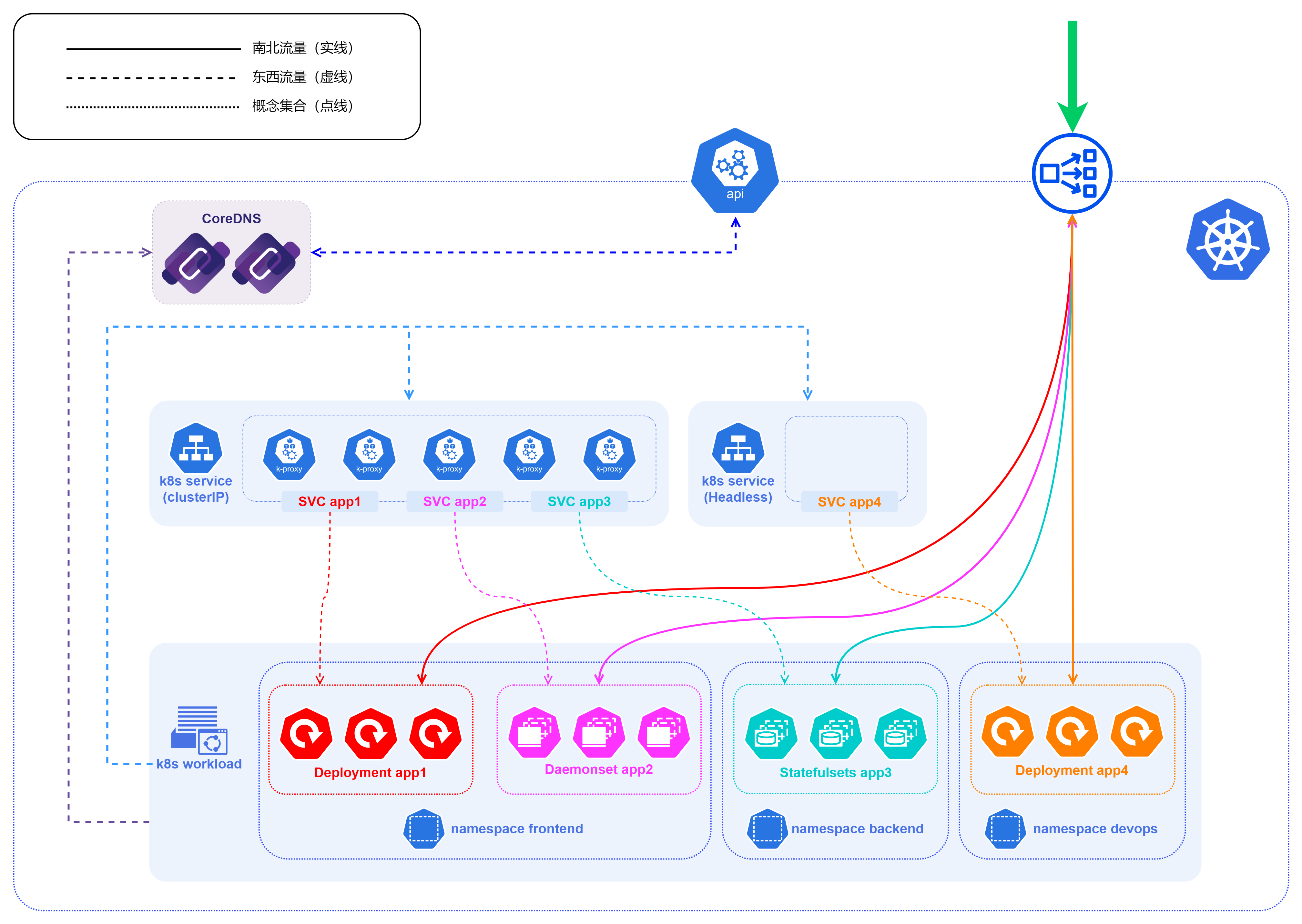
Let’s start from the bottom to the top
- The figure has multiple namespaces such as
frontend,backend,devops, etc., which are common means to isolate different resources, and can be divided according to different businesses and people using them in actual landing scenarios, and the specific division dimensions and criteria are best depending on the actual business situation. - In fact, not only workload, service will also be divided according to different namespace, including most api in K8S cluster, we need to specify namespace when looking for
- In the k8s service layer, the diagram mainly shows the Cluster-IP and Headless methods for internal cluster access
- Note that the Headless service is exclusive to the other three service types, and it is not load balanced by kube-proxy, so the blue solid box for the Headless service is blank, while the Cluster-IP is the kube-proxy component
- CoreDNS can be used to provide naming services starting with v1.11 of K8S and replacing
kube-dnsas the default DNS service starting with v1.13. - In Kubernetes version 1.21, kubeadm removed support for using
kube-dnsas a DNS application. Forkubeadmv1.24, the only cluster DNS application supported is CoreDNS - CoreDNS itself is also a
workload, which is adeployments.appsin thekube-systemnamespace - CoreDNS also gets information about services within the k8s cluster by requesting the api-server within the k8s cluster
- Further up is located at the boundary of the entire K8S cluster, where there is inevitably an api-server that exposes the control interface to both inside and outside the cluster, and through which we can get information about the K8S cluster
- api-server itself does not store information, most of the cluster information of the K8S cluster itself is stored in the etcd service, and api-server will go to the etcd to read the relevant data and return it.
- The last is the service used to expose the four layers of services, usually NodePort or LoadBalancer, because of the port and IP and other reasons, most of them are actually exposed out in the way of LoadBalancer when they are used.
- The LoadBalancer service is not exposed to the outside world as an IP, but as an
IP+port, which means that actually multiple ports of an IP can provide services for different types of services, such as ports 80 and 443 for http/https services, 3306 for database services, etc. - K8S does not have a built-in LoadBalancer, so you need to implement LoadBalancer, currently there are two mainstream ways: one is to use the LoadBalancer provided by cloud vendors such as AWS, Azure, Ali Tencent, etc. These LoadBalancers are basically closed source solutions, basically only applicable to their own cloud environment The second is to use some existing open source LoadBalancer, mainly MetalLB, OpenELB and PureLB.
- Open source LoadBalancer basically has two main modes of operation: Layer2 mode and BGP mode. Whether Layer2 mode or BGP mode, the core idea is to somehow direct traffic from a specific VIP to the k8s cluster, and then forward the traffic to a specific service behind it via kube-proxy.
5, seven-tier service exposure
The advantage of the four-tier LoadBalancer service exposure approach is that it is widely applicable, because it works on four tiers and therefore can be adapted to almost all types of applications. But there are also some disadvantages.
- For most application scenarios are http protocol requests, it is not necessary to configure an
EXTERNAL-IPfor each service to expose the service, which is a serious waste of resources (public IP is very precious), and includes IP address has been HTTPS using certificate management, etc. are very troublesome - A more common scenario is to configure a domain name (virtual host) or routing rule for each configuration, then expose one or a few
EXTERNAL-IPsto the public, and import all the request traffic to a centralized entry gateway (e.g. Nginx), which will then perform various load balancing, routing rule, certificate management (SSL termination), etc.
In K8S, these things are generally done by ingress.
5.1 Ingress
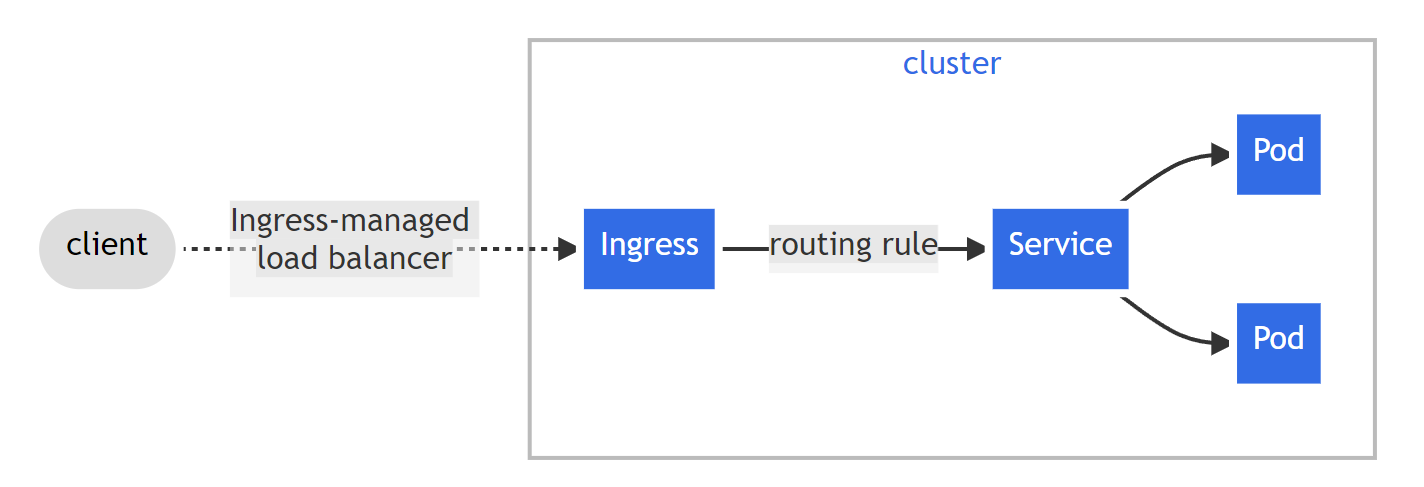
Ingress is an API object that manages external access to services in a cluster, typically through HTTP. Ingress can provide load balancing, routing rule, certificate management (SSL termination), etc. Ingress exposes HTTP and HTTPS routing from outside the cluster to services within the cluster. Traffic routing is controlled by rules defined on Ingress resources.
The following diagram is an official K8S diagram of how ingress works.
Here we need to pay attention to the distinction between Ingress and Ingress Controllers, which are two different concepts and are not equivalent
- From a conceptual point of view,
Ingressis very similar to the aforementioned service, and Ingress itself is not a real workload. - And
Ingress Controllersare more inclined to be deployed in K8S clusters with some special gateways (such as NGX), take the officially maintainedingress-nginxof K8S as an example, it is essentially is actually a special deployments with Ingress resource type, andIngress Controllersis a concrete implementation ofIngress.
5.2 Ingress Controllers
We learned above that the so-called Ingress Controllers themselves are actually special workloads (generally deployment), so they themselves need to be exposed to the cluster in some way in order to provide services, and here they are generally chosen to be exposed through LoadBalancer for four layers of services.
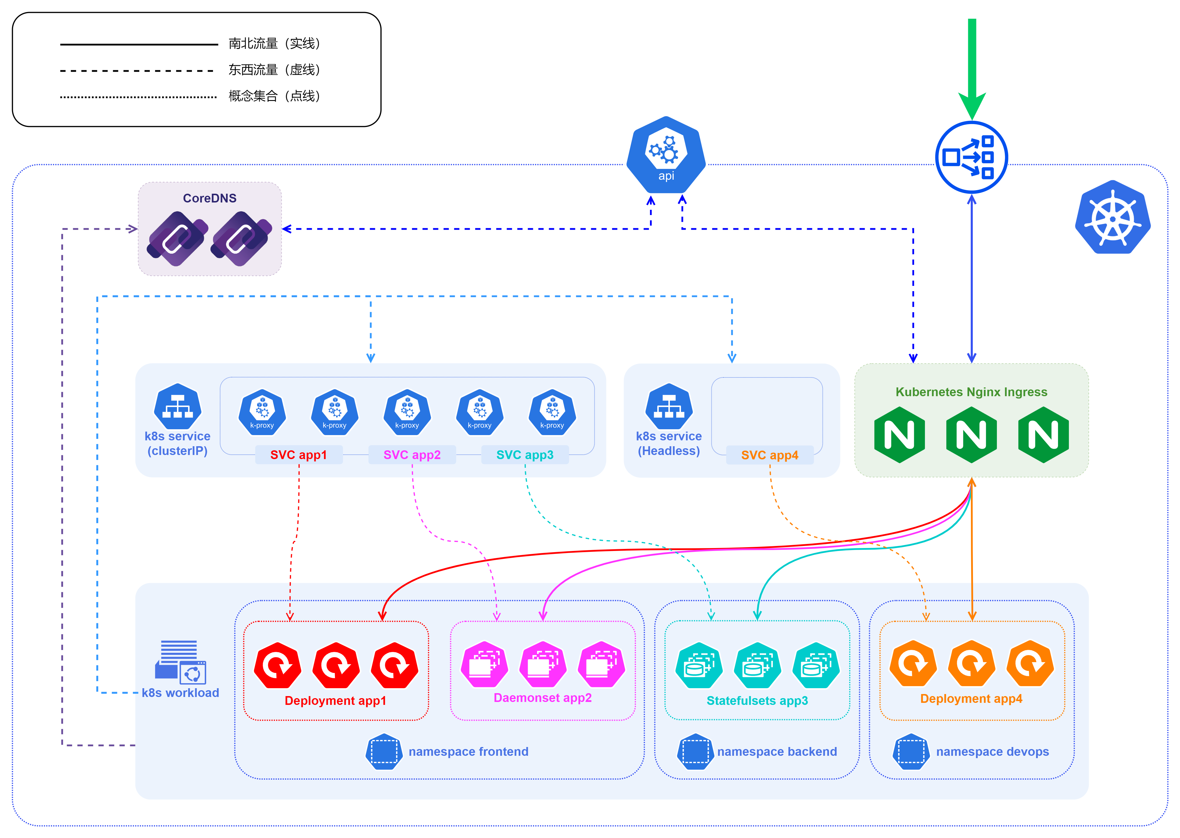
For the above four-layer service exposure architecture diagram, we add an Ingress after the LoadBalancer at the entrance to get the seven-layer Ingress service exposure architecture diagram.
- The processing logic in this diagram is the same as the four-tier service exposure, the only difference is that the HTTP protocol traffic is first passed through the loadbalancer at the entrance and then forwarded to the ingress, which is then forwarded according to the ingress rule inside to make a judgment.
- The ingress-nginx of k8s will communicate with the api-server in the cluster and get the service information, because
Ingress Controllersitself has the ability of load balancing, so when forwarding the traffic to the specific service in the backend, it will not go through the ClusterIP (even if the service type is ClusterIP). does not pass through), but is forwarded directly to thePod IPto which it belongs.
6. Summary
Here the basic service exposure of K8S need to understand the knowledge is introduced. Since K8S itself is indeed very complex, this article can only scratch the surface when introducing it. With the continuous development of K8S, the ordinary service exposure is now not good enough to meet the high-end needs of some scenarios, which then triggered a lot of evolution such as service mesh, sidecar, sidecarless, and so on.