In this paper, we will explore the network models in Kubernetes, as well as analyze various network models.
Underlay Network Model
What is Underlay Network
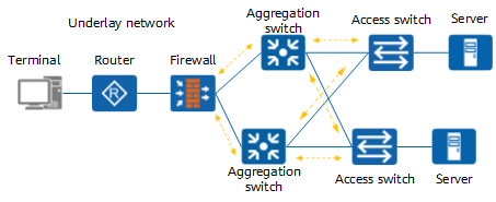
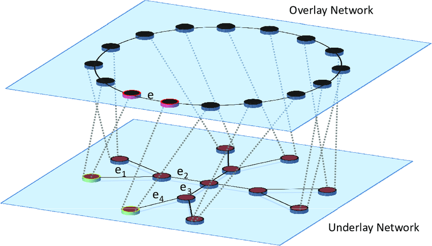
Underlay Network as the name suggests is the physical network topology that the network equipment infrastructure such as switches, routers, DWDM are linked into using the network media that is responsible for the transmission of packets between networks.
The underlay network can be either layer 2 or layer 3; a typical example of a layer 2 underlay network is Ethernet Ethernet, and a typical example of a layer 3 being an underlay network is the Internet Internet.
While the technology that works with layer 2 is vlan, the technology that works with layer 3 is composed of protocols such as OSPF, BGP, etc.
Underlay network in kubernetes
A typical example of underlay network in kubernetes is by using the host as a router device, while the Pod’s network learns to communicate across nodes by becoming a routed entry.
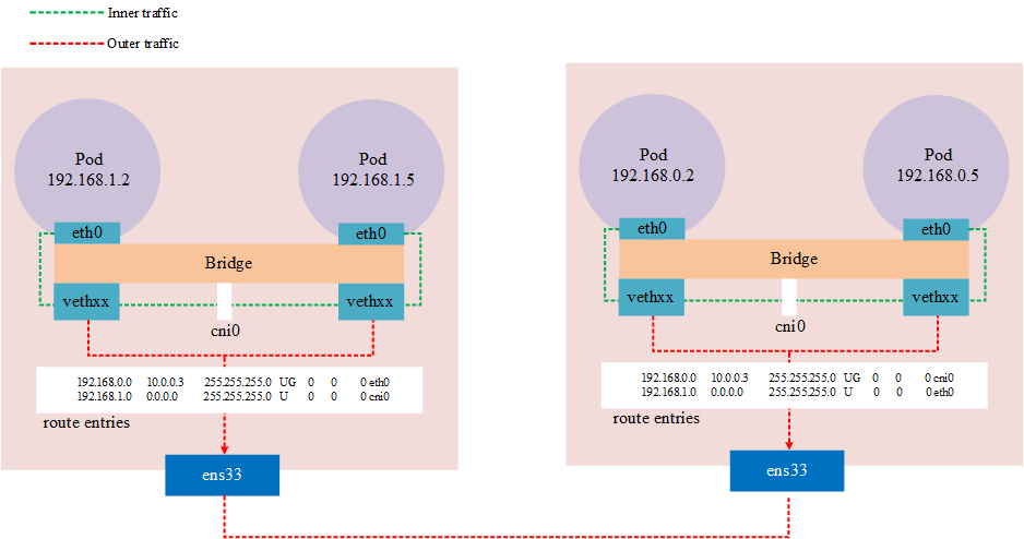
Typical under this model are flannel’s host-gw mode and calico BGP mode.
flannel host-gw
In flannel host-gw mode, each Node needs to be in the same Layer 2 network, and the Node is used as a router, and cross-node communication is done through routing tables. This way the network is modeled as an underlay network.
Source: https://www.auvik.com/franklyit/blog/layer-3-switches-layer-2/
Because it is by routing, the cidr of the cluster should be configured at least 16, because this ensures that the Node across nodes acts as a layer of network and the Pod of the same node acts as a network. If this is not the use case, the routing table is in the same network and there will be network unreachability.
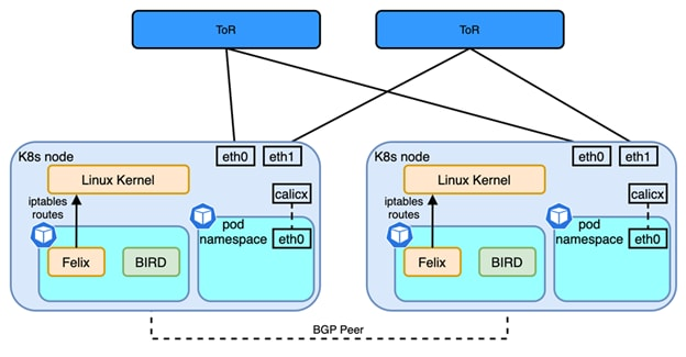
Calico BGP
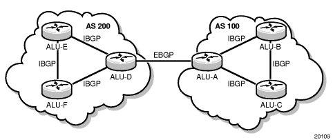
BGP (Border Gateway Protocol) is a decentralized autonomous routing protocol. It is a vector routing protocol that achieves accessibility between AS (Autonomous System) by maintaining IP routing tables or ‘prefix’ tables.
Source:https://infocenter.nokia.com/public/7705SAR214R1A/index.jsp?topic=%2Fcom.sar.routing_protocols%
Unlike flannel, which provides a BGP network solution, Calico is similar to Flannel host-gw in terms of network model, but in terms of software architecture implementation, flannel uses flanneld processes to maintain routing information; whereas Calico contains The Brid process is a BGP client with a Router Reflector. The BGP client is responsible for fetching routes from Felix and distributing them to other BGP Peers, while the reflector plays an optimization role in BGP. Within the same IBGP, BGP clients need to be connected to only one RR, which reduces the large number of BGP connections maintained within the AS. Typically, the RR is the real routing device, and the Bird works as a BGP client.
Source: https://www.cisco.com/c/en/us/td/docs/dcn/whitepapers/cisco-nx-os-calico-network-design.html
IPVLAN & MACVLAN
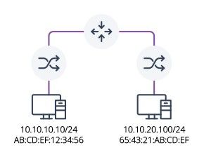
IPVLAN and MACVLAN are a type of NIC virtualization technology. The difference between the two is that IPVLAN allows a physical NIC to have multiple IP addresses and the same MAC address for all virtual interfaces, while MACVLAN is the opposite, allowing the same NIC to have multiple MAC addresses and the virtualized NIC can have no IP address.
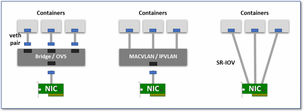
Because it is a NIC virtualization technology, not a network virtualization technology, it is essentially an Overlay network. The biggest feature of this approach compared to Overlay network in a virtualized environment is that it can level the Pod’s network to the same level of the Node network, thus providing a higher performance, low-latency network interface. Essentially its network model belongs to the second one in the figure below.
- Virtual Bridge: Create a virtual NIC pair (veth pair), one in the container and one in the root namespaces of the host. In this way, packets sent from the container can enter the host network stack directly through the bridge, and packets sent to the container can also enter the container through the bridge.
- Multiplexing: Using an intermediate network device that exposes multiple virtual NIC interfaces, container NICs can all intervene in this intermediate device and distinguish which container device a packet should be sent to by MAC/IP address.
- Hardware switching, assigning a virtual NIC to each Pod, so that the connection between Pod and Pod becomes very clear, as the basis for communication between near physical machines. Most NICs today support the SR-IOV feature, which virtualizes a single physical NIC into multiple VF interfaces, each with a separate virtual PCIe lane, and these virtual PCIe lanes share the PCIe lanes of the physical NIC.
Source: https://thenewstack.io/hackers-guide-kubernetes-networking/
Typical CNIs under this network model in kubernetes IPVLAN are, multus and danm.
multus
multus is intel’s open source CNI solution that is made from legacy cni with multus and provides the SR-IOV CNI plug-in to enable the K8s pod to connect to the SR-IOV VF. This is using the IPVLAN/MACVLAN feature.
When a new Pod is created, the SR-IOV plugin starts working. The configuration VF will be moved to the new CNI namespace. The plug-in sets the interface name according to the “name” option in the CNI profile. Finally, the VF status is set to UP.
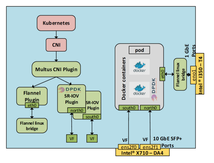
The following diagram shows a network environment for Multus and SR-IOV CNI plugins with three interface pods.
- eth0 is the flannel network plug-in, and is also used as the default network for Pods
- VF is an instantiation of the host’s physical port ens2f0. This is a port on the Intel X710-DA4. The VF interface name on the Pod side is south0.
- This VF uses the DPDK driver, and this VF is instantiated from the physical port ens2f1 of the host. This is an additional port on the Intel® X710-DA4. The name of the VF interface within the Pod is north0. This interface is bound to the DPDK driver vfio-pci.
Source: https://builders.intel.com/docs/networkbuilders/enabling_new_features_in_kubernetes_for_NFV.pdf
Notes: terminology
- NIC: Network interface controller
- SR-IOV: single root I/O virtualization, a hardware-implemented function that allows PCIe devices to be shared among virtual machines.
- VF: Virtual Function, based on PF, shares a physical resource with PF or other VFs.
- PF: PCIe Physical Function, has full control of PCIe resources
- DPDK: Data Plane Development Kit
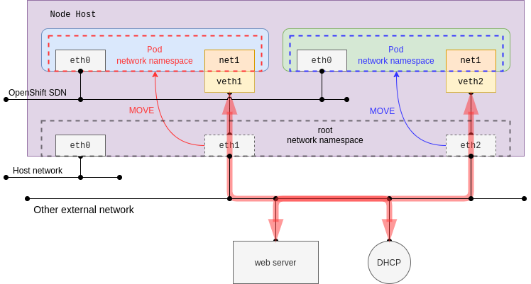
At the same time, it is possible to move the host interface directly into the Pod’s network namespace, but of course this interface must be present and cannot be the same interface as the default network. In this case, in a normal NIC environment, the Pod network is directly in the same plane as the Node network.
danm
DANM is Nokia’s open source CNI project, which aims to bring carrier-grade networking to kubernetes, providing the same hardware technology as multus, SR-IOV/DPDK, and supporting IPVLAN.
Overlay Network Mode
What is Overlay
An overlay network is a virtual logical network built on top of an underlay network using network virtualization technology, without requiring changes to the physical network architecture. Essentially, an overlay network uses one or more tunneling protocols (tunneling) to enable the transmission of packets from one network to another by encapsulating them, specifically tunneling protocols are concerned with packets (frames).
Common Network Tunneling Technologies
- Generic Routing Encapsulation ( Generic Routing Encapsulation) used to encapsulate packets from IPv4/IPv6 into packets from another protocol, usually works with the L3 network layer.
- VxLAN (Virtual Extensible LAN), a simple tunneling protocol, is essentially a way to encapsulate Ethernet frames from L2 into UDP packets in L4, using 4789 as the default port. VxLAN is also an extension of VLAN for 4096 (212-bit VLAN ID) extended to 16 million (224-bit VNID) logical networks.
This kind of work is typical for the overlay model with flannel and VxLAN in calico, IPIP mode.
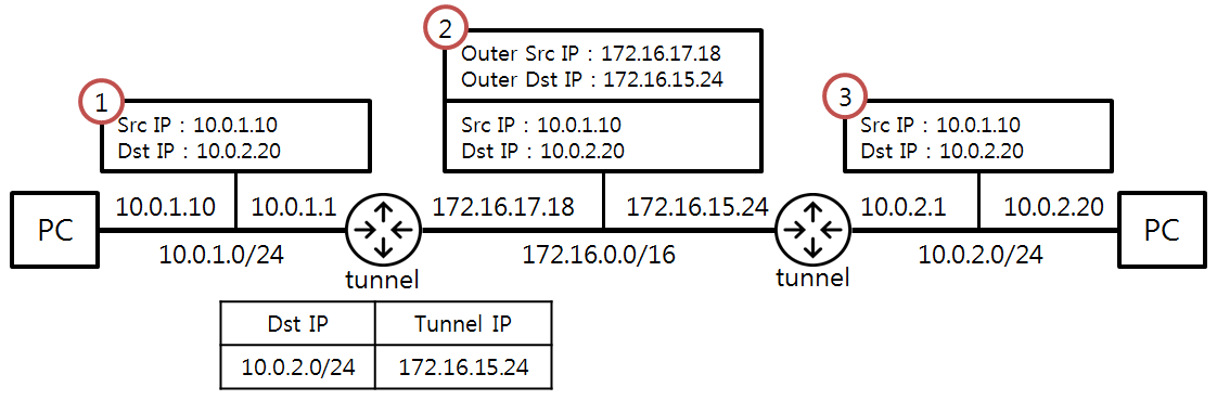
IPIP
IP in IP is also a tunneling protocol, and similar to VxLAN, the IPIP implementation is also encapsulated through Linux kernel functionality. IPIP requires the kernel module ipip.ko Use the command to see if the kernel loads the IPIP module lsmod | grep ipip; use the command modprobe ipip to load it.
Source: https://ssup2.github.io/theory_analysis/IPIP_GRE_Tunneling/
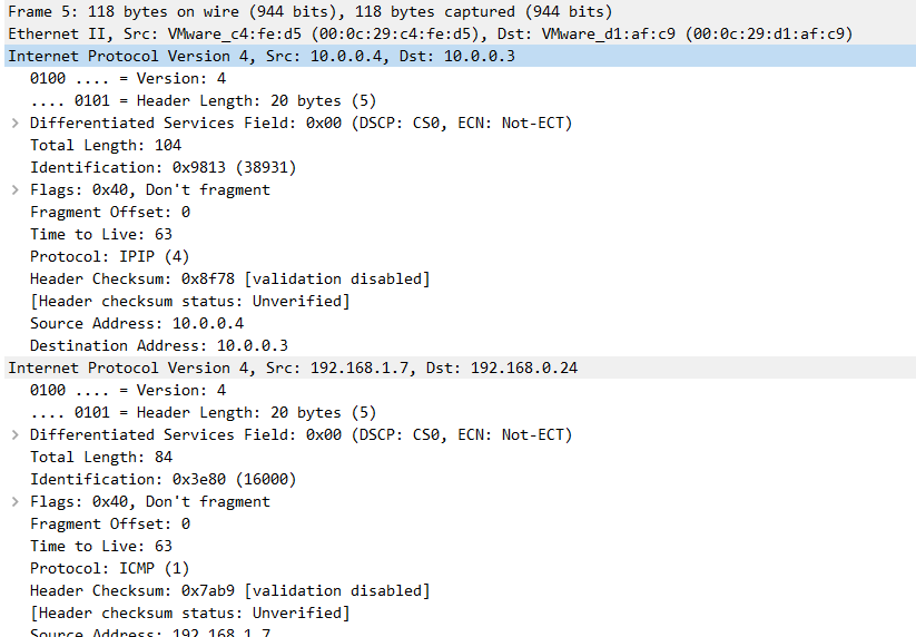
IPIP in Kubernetes is similar to VxLAN in that it is also implemented through network tunneling technology. The difference from VxLAN is that VxLAN is essentially a UDP packet, while IPIP encapsulates the packet on its own packet.
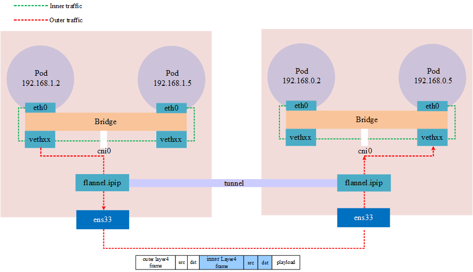
Notes: Public clouds may not allow IPIP traffic, such as Azure
VxLAN
Both the flannel and calico VxLAN implementations in kubernetes are wrappers using Linux kernel functionality. Linux support for the vxlan protocol was not long in coming, and it was only in 2012 that Stephen Hemminger merged the related work into the kernel, which eventually appeared in kernel version 3.7.0. For stability and many features, you may see some software recommending VxLAN on kernel versions 3.9.0 or 3.10.0 onwards.
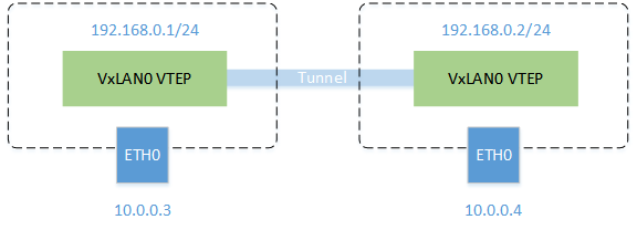
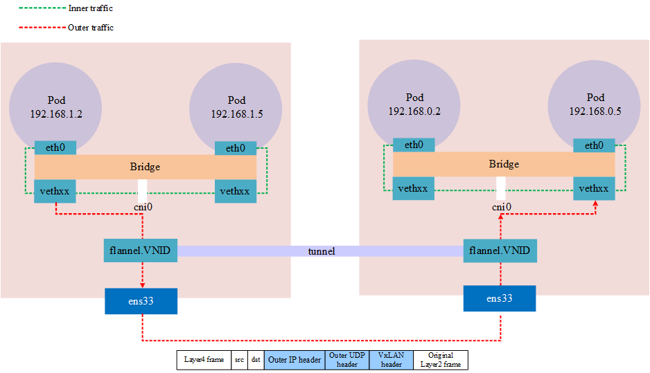
In a vxlan network in kubernetes, such as flannel, the daemon maintains VxLAN with the name flannel.1 which is the VNID according to the Node of kubernetes, and maintains the routes of this network. When cross-node traffic occurs, the MAC of the VxLAN device at the opposite end is maintained locally This address allows you to know the sending destination, so that you can seal the packet and send it to the other end, and the VxLAN device flannel.1 on the other end that receives the packet will unpack it and get the real destination address.
View the Forwarding database list.
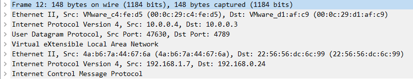
Notes: VxLAN uses port 4789, wireshark should be based on the port to analyze the protocol, and flannel in linux default port is 8472, at this time the capture packet can only see is a UDP packet.
The above architecture shows that tunneling is actually an abstract concept, not a real tunnel established at both ends, but a network overlay achieved by encapsulating a packet into another packet that is transmitted through a physical device and then unpacked via the same device (network tunnel).
weave vxlan
weave also uses VxLAN technology for packet encapsulation, which is called fastdp (fast data path) in weave, unlike the technology used in calico and flannel, which uses the Linux kernel’s openvswitch datapath module in the Linux kernel, and weave encrypts the network traffic.
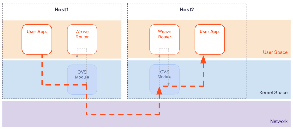
Source: https://www.weave.works/docs/net/latest/concepts/fastdp-how-it-works/
fastdp works on Linux kernel version 3.12 and higher, if it is lower than this version, for example CentOS7, weave will work in user space, which is called sleeve mode in weave