Through some of the previous notes, we have a basic understanding of how various container network models are implemented. However, what really pushes container technology to the climax is the Kubernetes container orchestration platform. Kubernetes forms clusters by integrating massive container instances, which may run in heterogeneous underlying network environments, and how to ensure the interoperability between these containers is one of the primary considerations in real production environments.
Kubernetes Network Basic Requirements
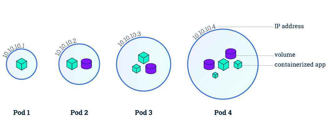
Kubernetes does more abstraction of container technology, one of the most important points is to propose the concept of pod, which is the basic unit of Kubernetes resource scheduling, we can simply think pod is an extension of container, from a network perspective, a pod must satisfy the following conditions.
- each pod has a unique IP address, and all pods are in a directly connectable, flat network space.
- all containers within the same pod share the same network namespace.
Based on such basic requirements, we can know that
- the ports are shared among all containers within the same pod and can be accessed directly through
localhost + port. - since each pod has a separate IP, there is no need to consider the mapping of container ports to host ports and port conflicts.
In fact, Kubernetes further defines the basic requirements for a qualified cluster network.
- that any two pods can in fact communicate directly with each other without explicit address translation using NAT.
- any cluster node and any pod can communicate directly with each other without the need for explicit address translation, and vice versa.
- any pod sees its own IP and others see it with the same IP, without address translation in between.
That is, the network model must meet all three of these things in order to be used in Kubernetes.
In fact, in the early days of Kubernetes, there were no networking standards, but only the above basic requirements. Based on this underlying network assumption, Kubernetes designed the classic three-tier pod-deployment-service access mechanism. It was not until the 1.1 release that Kubernetes began to adopt the new CNI (Container Network Interface) networking standard.
CNI
In fact, when we introduced container networks earlier, we mentioned the CNI network specification, which is less constrained and more open to developers than the CNM (Container Network Model) and does not depend on the container runtime. In fact, the CNI specification is very simple indeed, see here for details.
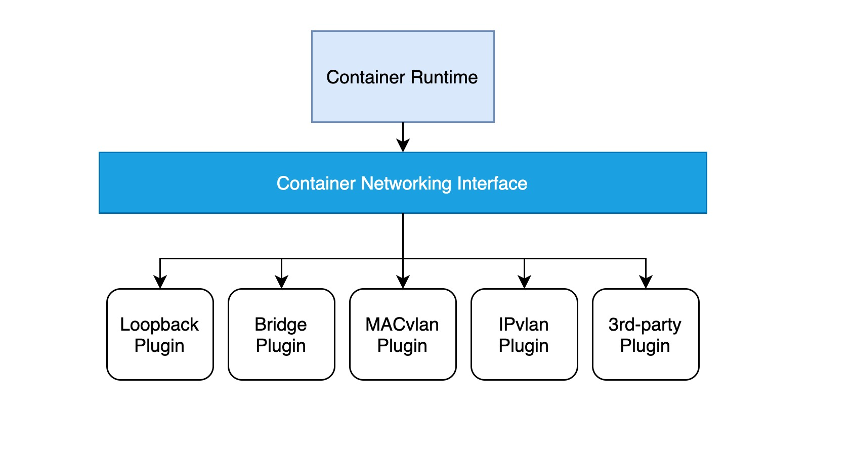
The implementation of a CNI web plug-in requires only a configuration file and an executable file.
- a configuration file describing basic information such as the version, name, and description of the plug-in.
- the executable is invoked by the higher-level container management platform, and a CNI executable needs to implement an ADD operation to add a container to the network and a DEL operation to remove a container from the network (and an optional VERSION view version operation).
The basic workflow of Kubernetes using the CNI network plugin.
- The kubelet first creates the pause container to create the corresponding network namespace.
- Calling specific CNI plug-ins according to the configuration can be configured as a chain of CNI plug-ins to make chain calls.
- When the CNI plug-in is invoked, it obtains the necessary information about the network namespace, the container’s network device, etc., based on environment variables and command line arguments, and then performs an ADD operation.
- The CNI plug-in configures the correct network for the pause container, and all other containers in the pod reuse the network of the pause container.
If you are not sure what a pause container is and where it is located in a pod, please see “From container to pod”.
pod network model
To understand how the Kubernetes network model is implemented, we need to start with individual pods. In fact, once you are familiar with the network model of a single pod, you will see that the Kubernetes network model basically follows the same principles as the container network model.
Through the previous notes “From container to pod”, we know that the pod starts by creating the pause container to create the corresponding network namespace, and then shares this network namespace with other containers. And for the network model of a single container we have introduced before, mainly through the docker0 bridge device and veth device pair connecting different container network namespace, thus, we can get a single pod network model as shown below.
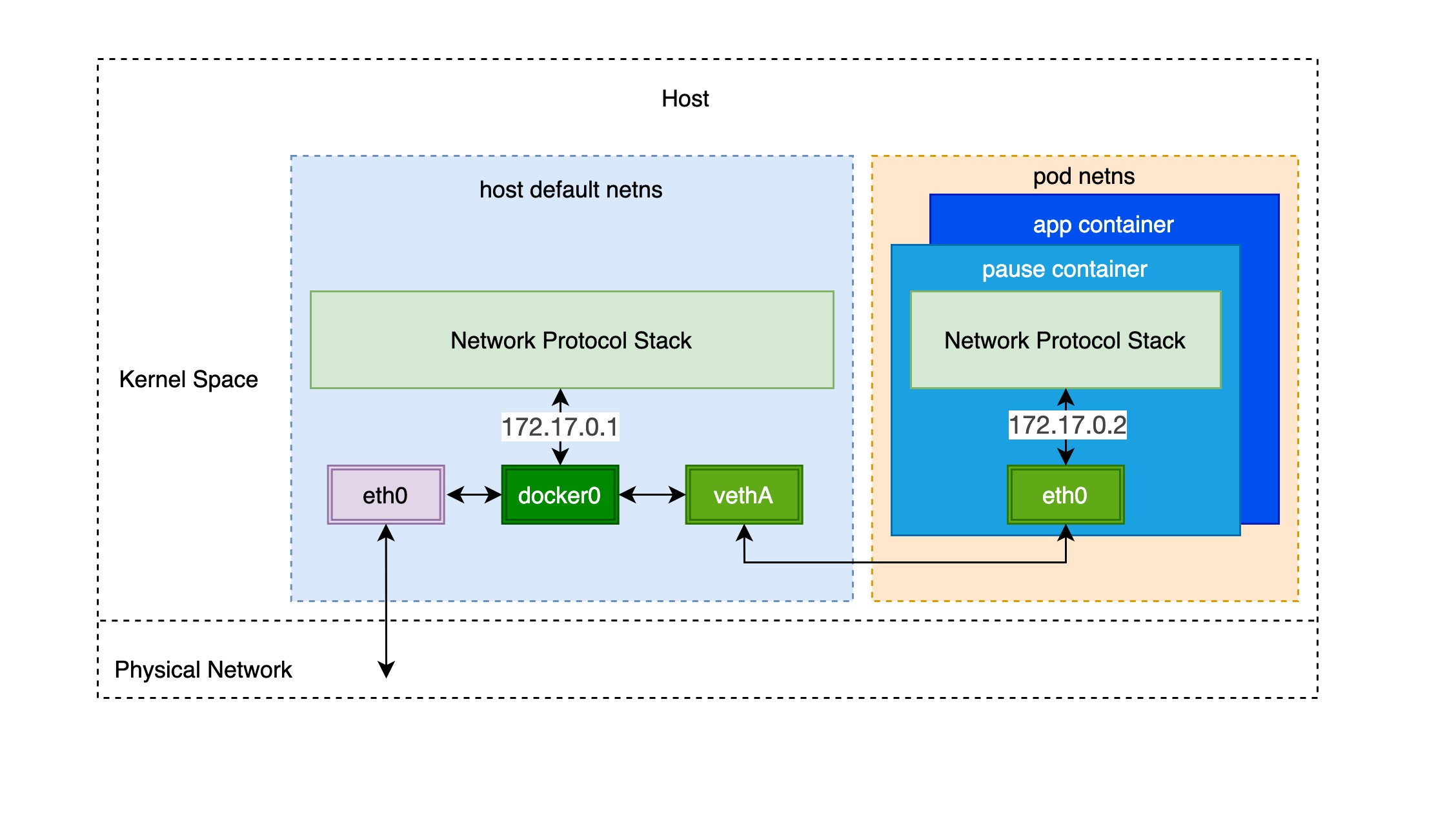
As you can see, other containers inside the same pod share the network namespace created by the pause container, that is, all containers share the same network device, routing table settings, service ports and other information, as if they were different processes running on the same machine, so these containers can communicate with each other directly through localhost + port; for requests from outside the cluster For requests from outside the cluster, the docker0 bridge device acts as a gateway and does address translation via iptables. Here we see that this is actually an extension of the bridge network model for a single container.
Mainstream Kubernetes Network Implementation Solutions
In the previous section, we knew that the network model of a single pod is an extension of the container network model, but how do pods communicate with each other? This is actually very similar to inter-container communication, and is divided into two cases: between pods on the same host and between pods across hosts.
As in the container network model. For direct communication between pods on the same host, via the docker0 bridge device on a direct Layer 2 (data link layer) network via MAC address.
And there are two main ideas to communicate between pods across hosts.
-
Modify the underlying network device configuration, add the management of container network IP address, modify the router gateway, etc. This approach is mainly combined with SDN (Software define networking).
-
Do not modify the underlying network device configuration at all, reuse the original underlay network plane. There are two main ways to solve the cross-host communication of containers.
-
Tunneling (overlay): Encapsulate container packets into Layer 3 or Layer 4 packets of the original host network, then use IP or TCP/UDP of the host network to transmit to the target host, and then forward to the target container after the target host has unpacked the packets. overlay tunneling common solutions include Vxlan, ipip, etc. Currently, the mainstream container networks using overlay tunneling technology include Flannel, etc.
-
Modify host routing: add the container network to the host routing table, use the host network device as a container gateway, and forward it to the specified host through routing rules to achieve three-tier inter-communication of containers. Current networks that implement container cross-host communication through routing techniques such as Flannel host-gw, Calico, etc..
-
The following is a brief description of several mainstream solutions.
- Flannel is currently the most commonly used scheme, providing a variety of network backends, which supports multiple data paths and is also suitable for a variety of scenarios such as overlay/underlay. For overlay packet encapsulation, you can use user-state UDP, kernel-state Vxlan (relatively good performance), or even host-gw to modify the host routing table when the cluster is small and in the same Layer 2 domain.
- Weave works very similarly to Flannel in that it first provided a UDP-only (called sleeve mode) network approach, and later added a fastpass approach (based on VxLAN), but Weave eliminates the extra components used to store network addresses in Flannel and integrates its own highly available data storage capabilities. Calico mainly uses modified host routing and BGP protocol to synchronize routes between nodes, but real networks do not always support BGP routing, so Calico also supports IPIP mode in the kernel and uses overlay to transfer data.
The following table compares several of the leading Kubernetes networking solutions.
| A | Overlay-Network | Host-RouteTable | NetworkPolicy Support | Decentralized IP Allocation |
|---|---|---|---|---|
| Flannel | UDP/VXLAN | Host-GW | N | N |
| Weave | UDP/VXLAN | N/A | Y | Y |
| Calico | IPIP | BGP | Y | N |
Policy Control (Network Policy)
Network Policy is a policy-based network control provided by Kubernetes to isolate applications and improve security. It uses the tag selector commonly used in Kubernetes to emulate traditional segmented networks and controls east-west traffic between them and north-south traffic with external communication via policy.
Note: Make sure the network plugin you are using supports Network Policy, for example, Flannel does not implement Network Policy.
The following example is an instance of configuring a typical Network Policy.
|
|
It uses the tag selectors namespaceSelector and posSelector to control the traffic between pods. The behavior pattern of the traffic is mainly determined by the following three objects.
- control object: filtered by
spec.podSelector - traffic direction:
ingresscontrols incoming pod traffic,egresscontrols outgoing pod traffic - traffic characteristics: end-to-end-IP-protocol-port
Precise control of incoming and outgoing traffic can be achieved by using Network Policy. It uses various selectors to find a set of pods that meet the conditions, or find the equivalent of two ends of communication, and then determines whether they can be connected to each other by characterizing the traffic, which can be understood as a whitelisting mechanism.