The essence of a container is a special process, special in that it creates a NameSpace isolated runtime environment and uses Cgroups to control resource overhead for it.
With these two underlying technologies, we can successfully implement application containerization, but how to make multiple containers in the network environment without interfering with each other can still communicate with each other, so that containers can access the external network, so that the external network can access a specific container and so on. These container network issues also have to take advantage of some Linux network virtualization techniques.
Container Network Isolation: NameSpace
Keeping the network environments of multiple containers from interfering with each other can be a continuation of the previous knowledge point on NameSpace.
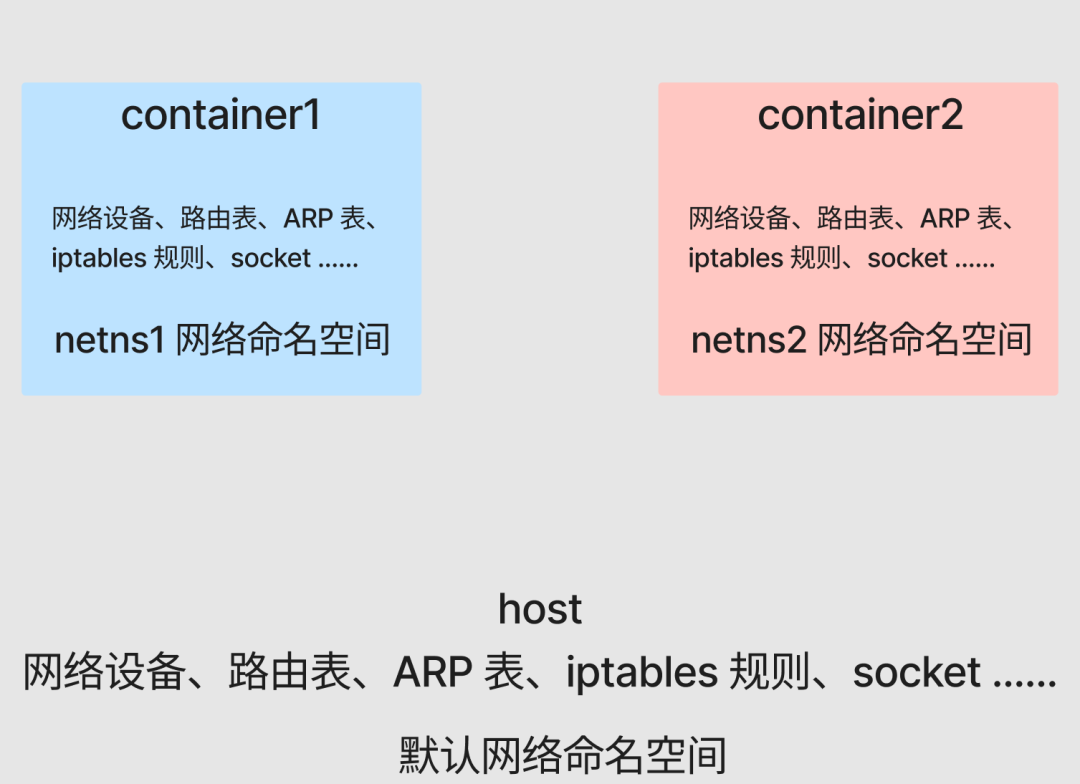
Among the 8 types of NameSpace introduced earlier, there is a Network NameSpace, with which we can configure a separate network view for containers.
Let’s look at the Default Network NameSpace where the host is located.
1
2
3
|
[root@host ~]# readlink /proc/$$/ns/net
net:[4026531956]
[root@host ~]#
|
Take net:[4026531956] for example, net represents the type of NameSpace, and 4026531956 is the inode number of NameSpace.
After the previous article, we already know that the essence of the container is the process, and this article will not go into detail. The next operation will go straight through the upper layers to the essence, exploring and restoring the implementation of the container network with the help of the capabilities provided by the underlying Linux layer. (Subsequent processes created in this article, please understand directly as a container)
First create two network namespaces, netns1 and netns2, with the ip netns tool.
1
2
3
4
5
6
|
[root@host ~]# ip netns add netns1
[root@host ~]# ip netns add netns2
[root@host ~]# ip netns list
netns2
netns1
[root@host ~]#
|
Create two bash process containers on top of each of these two network namespaces.
container1:
 1
 2
 3
 4
 5
 6
 7
 8
 9
10
11
12
13
14
15
16
17
18
19
|
[root@host ~]# ip netns exec netns1 /bin/bash --rcfile <(echo "PS1=\"container1> \"")
container1> readlink /proc/$$/ns/net
net:[4026532165]
container1> ip link # View the list of network devices
1: lo: <LOOPBACK> mtu 65536 qdisc noop state DOWN mode DEFAULT group default qlen 1000
    link/loopback 00:00:00:00:00:00 brd 00:00:00:00:00:00
container1> route -n # View routing table
Kernel IP routing table
Destination     Gateway         Genmask         Flags Metric Ref    Use Iface
container1> iptables -L # View iptables rules
Chain INPUT (policy ACCEPT)
target     prot opt source               destination

Chain FORWARD (policy ACCEPT)
target     prot opt source               destination

Chain OUTPUT (policy ACCEPT)
target     prot opt source               destination
container1>
|
container2:
 1
 2
 3
 4
 5
 6
 7
 8
 9
10
11
12
13
14
15
16
17
18
19
|
[root@host ~]# ip netns exec netns2 /bin/bash --rcfile <(echo "PS1=\"container2> \"")
container2> readlink /proc/$$/ns/net
net:[4026532219]
container2> ip link # View the list of network devices
1: lo: <LOOPBACK> mtu 65536 qdisc noop state DOWN mode DEFAULT group default qlen 1000
    link/loopback 00:00:00:00:00:00 brd 00:00:00:00:00:00
container2> route -n # View routing table
Kernel IP routing table
Destination     Gateway         Genmask         Flags Metric Ref    Use Iface
container2> iptables -L # View iptables rules
Chain INPUT (policy ACCEPT)
target     prot opt source               destination

Chain FORWARD (policy ACCEPT)
target     prot opt source               destination

Chain OUTPUT (policy ACCEPT)
target     prot opt source               destination
container2>
|
As you can see, due to the Network NameSpace isolation, different containers (container1 and container2) have their own independent network stack, including network devices, routing tables, ARP tables, iptables rules, sockets, etc. All containers will think they are running in a separate network environment.
Now prepare a simple go web service and run it in the background of container1 and container2 respectively.
 1
 2
 3
 4
 5
 6
 7
 8
 9
10
11
12
13
14
15
16
17
|
package main

import (
 "fmt"
 "net/http"
 "os"
)

func main() {
 name := os.Args[1]
 http.HandleFunc("/", func(w http.ResponseWriter, r *http.Request) {
  fmt.Println("req")
  w.Write([]byte(name + "\n"))
 })
 fmt.Println(name, "listen :8080")
 panic(http.ListenAndServe(":8080", nil))
}
|
container1:
1
2
3
4
5
|
container1> go run main.go container1 > container1.log &
[1] 2866
container1> tail container1.log
container1 listen :8080
container1>
|
container2:
1
2
3
4
5
6
|
container2> go run main.go container2 > container2.log &
[1] 2955
container2> tail container2.log
container2 listen :8080
container2>
|
Currently, there is no port conflict between container1 and container2 on the same host, even if they are both listening on port 8080.
Let’s test the availability of the service we just started, using container1 as an example.
1
2
3
4
|
container1> curl localhost:8080
curl: (7) Failed to connect to ::1: Network is unreachable
container1>
|
The connection fails at this point because we haven’t enabled any network devices at all, including our basic lo loop device. Just enable them directly.
 1
 2
 3
 4
 5
 6
 7
 8
 9
10
11
12
13
14
15
|
container1> ifconfig
container1> ifup lo
container1> ifconfig
lo: flags=73<UP,LOOPBACK,RUNNING>  mtu 65536
        inet 127.0.0.1  netmask 255.0.0.0
        inet6 ::1  prefixlen 128  scopeid 0x10<host>
        loop  txqueuelen 1000  (Local Loopback)
        RX packets 0  bytes 0 (0.0 B)
        RX errors 0  dropped 0  overruns 0  frame 0
        TX packets 0  bytes 0 (0.0 B)
        TX errors 0  dropped 0 overruns 0  carrier 0  collisions 0

container1> curl localhost:8080
container1
container1>
|
container2 Similarly.
Container Peer-to-Peer Communication: Veth
Currently two containers are in different Network NameSpace, their network environment is isolated from each other, you don’t know me and I don’t know you, naturally they can’t communicate with each other over the network.
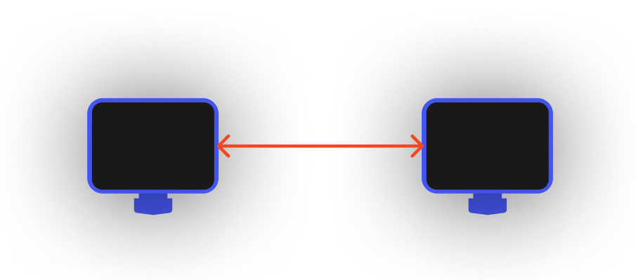
Before we get into the solution, let’s recall that in the real world, if two computers need to communicate with each other over the network.

We just need to connect the two computers directly with a network cable and that’s it.
So back to the container level, let’s abstract a bit, can containers also have a similar network port can be used to “plug a network cable”?
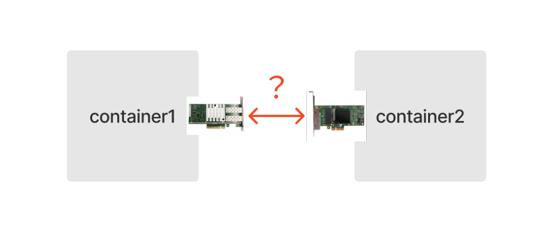
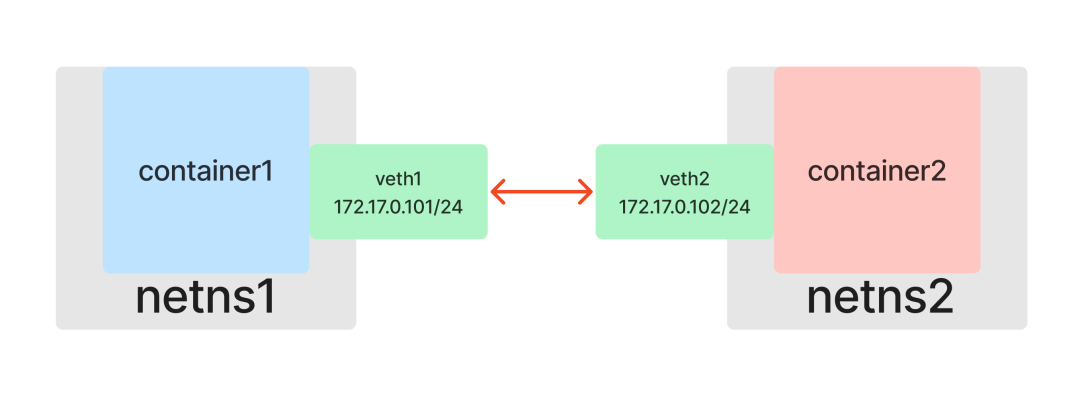
The answer is of course yes, and Linux network virtualization technology provides us with a way to emulate hardware NICs with software: Veth (Virtual Ethernet devices).
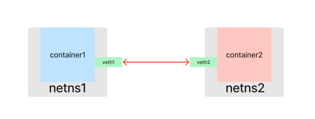
Like a network cable with two ends, Veths come in pairs, so they are also called veth pairs. Assuming that veth1 and veth2 are a pair of devices, packets coming in from veth1 will be received at veth2 and vice versa. So if you put a pair of Veth into two Network Namespaces, the two Network Namespaces will be able to communicate with each other as if they were connected to a network cable.
To start the practice, first look at the list of existing network devices on the host.
1
2
3
4
5
6
|
[root@host ~]# ip link
1: lo: <LOOPBACK,UP,LOWER_UP> mtu 65536 qdisc noqueue state UNKNOWN mode DEFAULT group default qlen 1000
    link/loopback 00:00:00:00:00:00 brd 00:00:00:00:00:00
2: eth0: <BROADCAST,MULTICAST,UP,LOWER_UP> mtu 1500 qdisc mq state UP mode DEFAULT group default qlen 1000
    link/ether 52:54:00:26:eb:d4 brd ff:ff:ff:ff:ff:ff
[root@host ~]#
|
Create a veth pair (containing both veth1 and veth2 virtual network devices).
 1
 2
 3
 4
 5
 6
 7
 8
 9
10
11
|
[root@host ~]# ip link add veth1 type veth peer name veth2
[root@host ~]# ip link
1: lo: <LOOPBACK,UP,LOWER_UP> mtu 65536 qdisc noqueue state UNKNOWN mode DEFAULT group default qlen 1000
    link/loopback 00:00:00:00:00:00 brd 00:00:00:00:00:00
2: eth0: <BROADCAST,MULTICAST,UP,LOWER_UP> mtu 1500 qdisc mq state UP mode DEFAULT group default qlen 1000
    link/ether 52:54:00:26:eb:d4 brd ff:ff:ff:ff:ff:ff
3: veth2@veth1: <BROADCAST,MULTICAST,M-DOWN> mtu 1500 qdisc noop state DOWN mode DEFAULT group default qlen 1000
    link/ether 6a:01:c8:fa:9e:6e brd ff:ff:ff:ff:ff:ff
4: veth1@veth2: <BROADCAST,MULTICAST,M-DOWN> mtu 1500 qdisc noop state DOWN mode DEFAULT group default qlen 1000
    link/ether 42:7e:de:c6:89:ff brd ff:ff:ff:ff:ff:ff
[root@host ~]#
|
Put the virtual NIC veth1 directly into the netns1 namespace on one end and veth2 into the netns2 namespace on the other end, which is equivalent to using a network cable to connect the two namespaces.
1
2
3
|
[root@host ~]# ip link set veth1 netns netns1
[root@host ~]# ip link set veth2 netns netns2
[root@host ~]#
|
Once connected, you can view the corresponding network devices in the container1 and container2 containers.
1
2
3
4
5
6
|
container1> ip link
1: lo: <LOOPBACK,UP,LOWER_UP> mtu 65536 qdisc noqueue state UNKNOWN mode DEFAULT group default qlen 1000
    link/loopback 00:00:00:00:00:00 brd 00:00:00:00:00:00
4: veth1@if3: <BROADCAST,MULTICAST> mtu 1500 qdisc noop state DOWN mode DEFAULT group default qlen 1000
    link/ether 42:7e:de:c6:89:ff brd ff:ff:ff:ff:ff:ff link-netnsid 1
container1>
|
1
2
3
4
5
6
|
container2> ip link
1: lo: <LOOPBACK,UP,LOWER_UP> mtu 65536 qdisc noqueue state UNKNOWN mode DEFAULT group default qlen 1000
    link/loopback 00:00:00:00:00:00 brd 00:00:00:00:00:00
3: veth2@if4: <BROADCAST,MULTICAST> mtu 1500 qdisc noop state DOWN mode DEFAULT group default qlen 1000
    link/ether 6a:01:c8:fa:9e:6e brd ff:ff:ff:ff:ff:ff link-netnsid 0
container2>
|
Set the IP addresses for the two NICs separately so that they are in the same subnet 172.17.0.0/24, and then enable the NICs.
 1
 2
 3
 4
 5
 6
 7
 8
 9
10
11
12
13
14
15
16
17
18
19
20
21
|
container1> ip addr add 172.17.0.101/24 dev veth1
container1> ip link set dev veth1 up
container1> ifconfig
lo: flags=73<UP,LOOPBACK,RUNNING>  mtu 65536
        inet 127.0.0.1  netmask 255.0.0.0
        inet6 ::1  prefixlen 128  scopeid 0x10<host>
        loop  txqueuelen 1000  (Local Loopback)
        RX packets 10  bytes 942 (942.0 B)
        RX errors 0  dropped 0  overruns 0  frame 0
        TX packets 10  bytes 942 (942.0 B)
        TX errors 0  dropped 0 overruns 0  carrier 0  collisions 0

veth1: flags=4099<UP,BROADCAST,MULTICAST>  mtu 1500
        inet 172.17.0.101  netmask 255.255.255.0  broadcast 0.0.0.0
        ether 42:7e:de:c6:89:ff  txqueuelen 1000  (Ethernet)
        RX packets 0  bytes 0 (0.0 B)
        RX errors 0  dropped 0  overruns 0  frame 0
        TX packets 0  bytes 0 (0.0 B)
        TX errors 0  dropped 0 overruns 0  carrier 0  collisions 0

container1>
|
 1
 2
 3
 4
 5
 6
 7
 8
 9
10
11
12
13
14
15
16
17
18
19
20
21
22
|
container2> ip addr add 172.17.0.102/24 dev veth2
container2> ip link set dev veth2 up
container2> ifconfig
lo: flags=73<UP,LOOPBACK,RUNNING>  mtu 65536
        inet 127.0.0.1  netmask 255.0.0.0
        inet6 ::1  prefixlen 128  scopeid 0x10<host>
        loop  txqueuelen 1000  (Local Loopback)
        RX packets 10  bytes 942 (942.0 B)
        RX errors 0  dropped 0  overruns 0  frame 0
        TX packets 10  bytes 942 (942.0 B)
        TX errors 0  dropped 0 overruns 0  carrier 0  collisions 0

veth2: flags=4163<UP,BROADCAST,RUNNING,MULTICAST>  mtu 1500
        inet 172.17.0.102  netmask 255.255.255.0  broadcast 0.0.0.0
        inet6 fe80::6801:c8ff:fefa:9e6e  prefixlen 64  scopeid 0x20<link>
        ether 6a:01:c8:fa:9e:6e  txqueuelen 1000  (Ethernet)
        RX packets 6  bytes 516 (516.0 B)
        RX errors 0  dropped 0  overruns 0  frame 0
        TX packets 6  bytes 516 (516.0 B)
        TX errors 0  dropped 0 overruns 0  carrier 0  collisions 0

container2>
|
Test container1 and container2 containers accessing each other’s services.
1
|
container1> curl 172.17.0.102:8080container2container1>
|
1
|
container2> curl 172.17.0.101:8080container1container2>
|
Here, relying only on Veth, we get a peer-to-peer layer 2 network topology and the problem of container peer-to-peer communication is successfully solved.
Communicating with each other between containers: Bridge
We know that in the real world, there can’t be only two computers, and when a third, fourth, or even countless computers join the network environment, we can’t have so many network ports to connect to each other two by two. To solve this problem, the Layer 2 switch (or bridge) was invented.
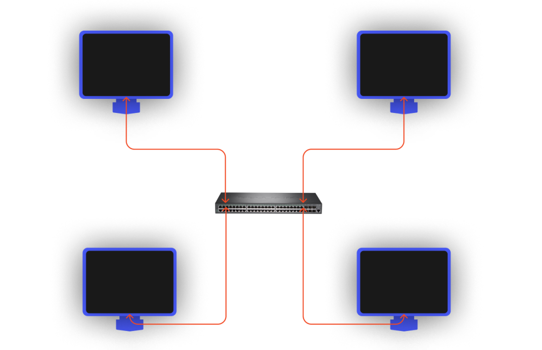
This is also true for containers, if we have 3 or more Namespaces that need access to the same layer 2 network, we can’t simply use Veth alone. However, just like using Veth as a virtual NIC, Linux also provides us with a virtual implementation of a bridge (switch): Bridge.
Create a netns3 namespace on top of the netns1 and netns2 namespaces.
1
2
3
4
5
6
|
[root@host ~]# ip netns add netns3
[root@host ~]# ip netns list
netns3
netns2 (id: 1)
netns1 (id: 0)
[root@host ~]#
|
Repeat the previous operation to create the container3 container.
 1
 2
 3
 4
 5
 6
 7
 8
 9
10
11
12
13
14
15
16
17
18
19
20
21
22
|
[root@host ~]# ip netns exec netns3 /bin/bash --rcfile <(echo "PS1=\"container3> \"")
container3> readlink /proc/$$/ns/net
net:[4026532277]
container3> go run main.go container3 > container3.log &
[1] 4270
container3> tail container3.log
container3 listen :8080
container3> ifup lo
container3> ifconfig
lo: flags=73<UP,LOOPBACK,RUNNING>  mtu 65536
        inet 127.0.0.1  netmask 255.0.0.0
        inet6 ::1  prefixlen 128  scopeid 0x10<host>
        loop  txqueuelen 1000  (Local Loopback)
        RX packets 0  bytes 0 (0.0 B)
        RX errors 0  dropped 0  overruns 0  frame 0
        TX packets 0  bytes 0 (0.0 B)
        TX errors 0  dropped 0 overruns 0  carrier 0  collisions 0

container3> curl localhost:8080
container3
container3>
|
Before we network the three containers to each other, we unplug the “network cables” (veth1 and veth2) that were previously connected between the container1 and container2 containers (only in one of the containers).
1
2
3
4
5
|
container1> ip link delete veth1
container1> ip link
1: lo: <LOOPBACK,UP,LOWER_UP> mtu 65536 qdisc noqueue state UNKNOWN mode DEFAULT group default qlen 1000
    link/loopback 00:00:00:00:00:00 brd 00:00:00:00:00:00
container1>
|
Now the three containers won’t know each other.
Back to practice, create a Bridge and enable it.
 1
 2
 3
 4
 5
 6
 7
 8
 9
10
11
12
13
14
15
16
17
18
19
20
21
22
23
24
25
26
27
28
29
30
31
32
33
34
35
36
37
|
[root@host ~]# ip link add br0 type bridge
[root@host ~]# ip link
1: lo: <LOOPBACK,UP,LOWER_UP> mtu 65536 qdisc noqueue state UNKNOWN mode DEFAULT group default qlen 1000
    link/loopback 00:00:00:00:00:00 brd 00:00:00:00:00:00
2: eth0: <BROADCAST,MULTICAST,UP,LOWER_UP> mtu 1500 qdisc mq state UP mode DEFAULT group default qlen 1000
    link/ether 52:54:00:26:eb:d4 brd ff:ff:ff:ff:ff:ff
5: br0: <BROADCAST,MULTICAST> mtu 1500 qdisc noop state DOWN mode DEFAULT group default qlen 1000
    link/ether 9e:ac:12:15:98:64 brd ff:ff:ff:ff:ff:ff
[root@host ~]# ip link set dev br0 up
[root@host ~]# ifconfig
br0: flags=4163<UP,BROADCAST,RUNNING,MULTICAST>  mtu 1500
        inet6 fe80::9cac:12ff:fe15:9864  prefixlen 64  scopeid 0x20<link>
        ether 9e:ac:12:15:98:64  txqueuelen 1000  (Ethernet)
        RX packets 0  bytes 0 (0.0 B)
        RX errors 0  dropped 0  overruns 0  frame 0
        TX packets 6  bytes 516 (516.0 B)
        TX errors 0  dropped 0 overruns 0  carrier 0  collisions 0

eth0: flags=4163<UP,BROADCAST,RUNNING,MULTICAST>  mtu 1500
        inet 10.0.12.15  netmask 255.255.252.0  broadcast 10.0.15.255
        inet6 fe80::5054:ff:fe26:ebd4  prefixlen 64  scopeid 0x20<link>
        ether 52:54:00:26:eb:d4  txqueuelen 1000  (Ethernet)
        RX packets 114601  bytes 160971385 (153.5 MiB)
        RX errors 0  dropped 0  overruns 0  frame 0
        TX packets 18824  bytes 2035143 (1.9 MiB)
        TX errors 0  dropped 0 overruns 0  carrier 0  collisions 0

lo: flags=73<UP,LOOPBACK,RUNNING>  mtu 65536
        inet 127.0.0.1  netmask 255.0.0.0
        inet6 ::1  prefixlen 128  scopeid 0x10<host>
        loop  txqueuelen 1000  (Local Loopback)
        RX packets 15  bytes 2000 (1.9 KiB)
        RX errors 0  dropped 0  overruns 0  frame 0
        TX packets 15  bytes 2000 (1.9 KiB)
        TX errors 0  dropped 0 overruns 0  carrier 0  collisions 0

[root@host ~]#
|
Prepare three “network cables” (three pairs of veth).
1
2
3
4
|
[root@host ~]# ip link add veth1 type veth peer name veth1-br
[root@host ~]# ip link add veth2 type veth peer name veth2-br
[root@host ~]# ip link add veth3 type veth peer name veth3-br
[root@host ~]#
|
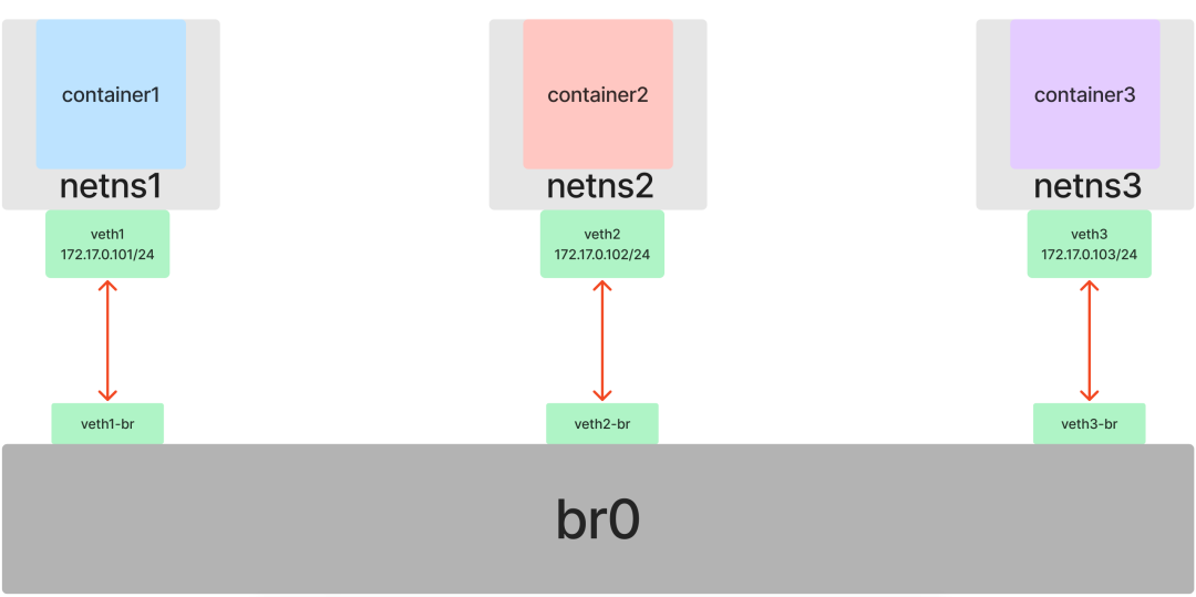
Insert veth1 into netns1, veth1-br into br0, veth2 into netns2, veth2-br into br0, veth3 into netns3, veth3-br into br0 (remember to enable veth*-br).
 1
 2
 3
 4
 5
 6
 7
 8
 9
10
|
[root@host ~]# ip link set dev veth1 netns netns1
[root@host ~]# ip link set dev veth2 netns netns2
[root@host ~]# ip link set dev veth3 netns netns3
[root@host ~]# ip link set dev veth1-br master br0
[root@host ~]# ip link set dev veth2-br master br0
[root@host ~]# ip link set dev veth3-br master br0
[root@host ~]# ip link set dev veth1-br up
[root@host ~]# ip link set dev veth2-br up
[root@host ~]# ip link set dev veth3-br up
[root@host ~]#
|
In each of the three containers, set the IP addresses for the respective NICs in the same subnet 172.17.0.0/24, and enable them as well after setting.
1
|
container1> ip addr add 172.17.0.101/24 dev veth1container1> ip link set dev veth1 upcontainer1>
|
1
|
container2> ip addr add 172.17.0.102/24 dev veth2container2> ip link set dev veth2 upcontainer2>
|
1
|
container3> ip addr add 172.17.0.103/24 dev veth3container3> ip link set dev veth3 upcontainer3>
|
Test container1, container2, container3 containers accessing each other’s services.
1
2
3
4
5
|
container1> curl 172.17.0.102:8080
container2
container1> curl 172.17.0.103:8080
container3
container1>
|
1
2
3
4
5
|
container2> curl 172.17.0.101:8080
container1
container2> curl 172.17.0.103:8080
container3
container2>
|
1
2
3
4
5
|
container3> curl 172.17.0.101:8080
container1
container3> curl 172.17.0.102:8080
container2
container3>
|
At this point, by introducing the Bridge feature on top of Veth, we have connected multiple Namespaces to the same Layer 2 network, and the problem of inter-container communication has been successfully solved.
Containers communicating with external networks: route and iptables
So far, our experiments have been in the same subnet. However, real-world application scenarios require more containers to be able to interoperate with the outside.
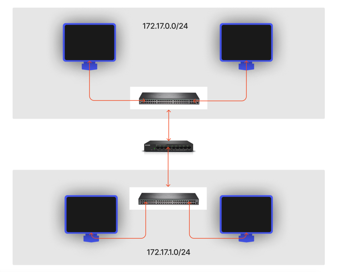
In the real world, a Layer 2 switch can only address data flow within the same subnet, for different subnets, a Layer 3 router (or gateway) needs to be used for forwarding.
However, unlike Bridge, which provides a virtualized implementation of a switch, Linux does not provide a virtual router device. Linux itself already has the function of a router and can be used directly as a router; more precisely, in Linux, a Network Namespace can assume the function of a router.
In Linux Network Namespace, the definition of the routing function is actually quite simple: directly by defining routing table rules, you can determine the flow of the requested packets to the specified network device.
Routing rules are defined in the routing table, for the routing table, we most commonly use local and main, of course, can also be configured in addition to other tables, where the local priority is higher than the main, we usually access the local machine (localhost) requests, will be directly in the local table to find the rules, and will not go through the main.
You can see all the routing tables.
 1
 2
 3
 4
 5
 6
 7
 8
 9
10
11
12
13
|
[root@host ~]# cat /etc/iproute2/rt_tables
#
# reserved values
#
255     local
254     main
253     default
0       unspec
#
# local
#
#1      inr.ruhep
[root@host ~]#
|
To view the rules in the specified routing table you can use the ip route list [table name]:
 1
 2
 3
 4
 5
 6
 7
 8
 9
10
11
12
13
14
15
16
17
18
19
|
[root@host ~]# ip route list table local
broadcast 10.0.12.0 dev eth0 proto kernel scope link src 10.0.12.15
local 10.0.12.15 dev eth0 proto kernel scope host src 10.0.12.15
broadcast 10.0.15.255 dev eth0 proto kernel scope link src 10.0.12.15
broadcast 127.0.0.0 dev lo proto kernel scope link src 127.0.0.1
local 127.0.0.0/8 dev lo proto kernel scope host src 127.0.0.1
local 127.0.0.1 dev lo proto kernel scope host src 127.0.0.1
broadcast 127.255.255.255 dev lo proto kernel scope link src 127.0.0.1
[root@host ~]# ip route list table main
default via 10.0.12.1 dev eth0
10.0.12.0/22 dev eth0 proto kernel scope link src 10.0.12.15
169.254.0.0/16 dev eth0 scope link metric 1002
[root@host ~]# route -n
Kernel IP routing table
Destination     Gateway         Genmask         Flags Metric Ref    Use Iface
0.0.0.0         10.0.12.1       0.0.0.0         UG    0      0        0 eth0
10.0.12.0       0.0.0.0         255.255.252.0   U     0      0        0 eth0
169.254.0.0     0.0.0.0         255.255.0.0     U     1002   0        0 eth0
[root@host ~]#
|
The route -n command we normally use is actually looking at the main routing table.
Interoperability between containers and hosts
We now have three containers, container1, container2 and container3, with IPs 172.17.0.101, 172.17.0.102 and 172.17.0.103 respectively, which are all on the same subnet.
Check the IP of the host, in this case 10.0.12.15.
 1
 2
 3
 4
 5
 6
 7
 8
 9
10
11
12
|
[root@host ~]# ifconfig
...
eth0: flags=4163<UP,BROADCAST,RUNNING,MULTICAST>  mtu 1500
        inet 10.0.12.15  netmask 255.255.252.0  broadcast 10.0.15.255
        inet6 fe80::5054:ff:fe26:ebd4  prefixlen 64  scopeid 0x20<link>
        ether 52:54:00:26:eb:d4  txqueuelen 1000  (Ethernet)
        RX packets 119923  bytes 161411733 (153.9 MiB)
        RX errors 0  dropped 0  overruns 0  frame 0
        TX packets 24106  bytes 2884317 (2.7 MiB)
        TX errors 0  dropped 0 overruns 0  carrier 0  collisions 0
...
[root@host ~]#
|
To view the routing rules for a container (container1, for example).
1
2
3
4
5
|
container1> route -n
Kernel IP routing table
Destination     Gateway         Genmask         Flags Metric Ref    Use Iface
172.17.0.0      0.0.0.0         255.255.255.0   U     0      0        0 veth1
container1>
|
It can be found that there is only one rule in the routing table of the current container: when accessing IPs in the 172.17.0.0/24 subnet, such as 172.17.0.102, the packets are forwarded directly to the veth1 device.
By the nature of Veth, the veth1-br device on the other end of the corresponding veth1 will receive the packet, and since the veth1-br device is connected to the br0 Layer 2 switch, the veth2-br device will also receive the packet, and finally it will reach the corresponding veth2 destination device.
Our goal now is to allow the container to forward packets when it accesses IPs other than those on the 172.17.0.0/24 subnet (e.g. host IP 10.0.12.15), which means we need to add routing rules to the container.
Recall our previous Bridge, from the network point of view, we treat it as a Layer 2 switch, so we don’t need to set IP address for it, but now from the host point of view, br0 is also a NIC in Default Network Namespace, we can directly set IP for this NIC to act as a Layer 3 router ( gateway) to participate in the routing and forwarding of the host.
We set the IP address of the br0 device to 172.17.0.1 on the host (also within subnet 172.17.0.0/24).
 1
 2
 3
 4
 5
 6
 7
 8
 9
10
11
12
|
[root@host ~]# ip addr add local 172.17.0.1/24 dev br0
[root@host ~]# ifconfig
br0: flags=4163<UP,BROADCAST,RUNNING,MULTICAST>  mtu 1500
        inet 172.17.0.1  netmask 255.255.255.0  broadcast 0.0.0.0
        inet6 fe80::9cac:12ff:fe15:9864  prefixlen 64  scopeid 0x20<link>
        ether 16:bd:7d:ca:53:bf  txqueuelen 1000  (Ethernet)
        RX packets 27  bytes 1716 (1.6 KiB)
        RX errors 0  dropped 0  overruns 0  frame 0
        TX packets 8  bytes 656 (656.0 B)
        TX errors 0  dropped 0 overruns 0  carrier 0  collisions 0
......
|
At this point, the host will automatically add a routing rule with a Destination of 172.17.0.0.
1
2
3
4
5
6
7
8
|
[root@host ~]# route -n
Kernel IP routing table
Destination     Gateway         Genmask         Flags Metric Ref    Use Iface
0.0.0.0         10.0.12.1       0.0.0.0         UG    0      0        0 eth0
10.0.12.0       0.0.0.0         255.255.252.0   U     0      0        0 eth0
169.254.0.0     0.0.0.0         255.255.0.0     U     1002   0        0 eth0
172.17.0.0      0.0.0.0         255.255.255.0   U     0      0        0 br0
[root@host ~]#
|
Following this routing rule (packets accessing a destination host of 172.17.0.0/24 are forwarded to the br0 device), we now have direct access to the container from the host.
 1
 2
 3
 4
 5
 6
 7
 8
 9
10
11
12
|
[root@host ~]# ping 172.17.0.101
PING 172.17.0.101 (172.17.0.101) 56(84) bytes of data.
64 bytes from 172.17.0.101: icmp_seq=1 ttl=64 time=0.025 ms
64 bytes from 172.17.0.101: icmp_seq=2 ttl=64 time=0.037 ms
64 bytes from 172.17.0.101: icmp_seq=3 ttl=64 time=0.031 ms
^C
--- 172.17.0.101 ping statistics ---
3 packets transmitted, 3 received, 0% packet loss, time 1999ms
rtt min/avg/max/mdev = 0.025/0.031/0.037/0.005 ms
[root@host ~]# curl 172.17.0.101:8080
container1
[root@host ~]#
|
Now that the host can access the container, back to the container accessing the host, we add route forwarding rules to the container so that by default all routes (0.0.0.0, except for IPs on the 172.17.0.0/24 subnet) need to forward packets through the br0 gateway (172.17.0.1) acting on layer 3.
1
2
3
4
5
6
7
|
container1> ip route add default via 172.17.0.1
container1> route -n
Kernel IP routing table
Destination     Gateway         Genmask         Flags Metric Ref    Use Iface
0.0.0.0         172.17.0.1      0.0.0.0         UG    0      0        0 veth1
172.17.0.0      0.0.0.0         255.255.255.0   U     0      0        0 veth1
container1>
|
This way, when the container accesses the host IP, the packet is forwarded directly to the br0 NIC of Default Network Namespace, and the host finds out that the received IP packet belongs to it and processes it.
This means that the container can now access the host as well.
 1
 2
 3
 4
 5
 6
 7
 8
 9
10
11
|
container1> ping 10.0.12.15
PING 10.0.12.15 (10.0.12.15) 56(84) bytes of data.
64 bytes from 10.0.12.15: icmp_seq=1 ttl=64 time=0.022 ms
64 bytes from 10.0.12.15: icmp_seq=2 ttl=64 time=0.031 ms
64 bytes from 10.0.12.15: icmp_seq=3 ttl=64 time=0.032 ms
^C
--- 10.0.12.15 ping statistics ---
3 packets transmitted, 3 received, 0% packet loss, time 1999ms
rtt min/avg/max/mdev = 0.022/0.028/0.032/0.006 ms
container1>
|
Container accessing other hosts (external network)
Above we have configured routing rules for the container to access the host IP, the packets will be forwarded to the br0 NIC of Default Network Namespace, and the host will process the received IP packets if they are found to belong to itself.
However, in Linux, if the received IP packet does not belong to the host, it will be discarded. Here we have prepared another host host2 with IP address 10.0.12.11 on the same subnet as the host (10.0.12.15) to test.
 1
 2
 3
 4
 5
 6
 7
 8
 9
10
11
12
13
14
15
16
17
18
19
20
|
[root@host2 ~]# ifconfig
eth0: flags=4163<UP,BROADCAST,RUNNING,MULTICAST>  mtu 1500
        inet 10.0.12.11  netmask 255.255.252.0  broadcast 10.0.15.255
        inet6 fe80::5054:ff:fe78:a238  prefixlen 64  scopeid 0x20<link>
        ether 52:54:00:78:a2:38  txqueuelen 1000  (Ethernet)
        RX packets 6103  bytes 2710292 (2.5 MiB)
        RX errors 0  dropped 0  overruns 0  frame 0
        TX packets 4662  bytes 640093 (625.0 KiB)
        TX errors 0  dropped 0 overruns 0  carrier 0  collisions 0

lo: flags=73<UP,LOOPBACK,RUNNING>  mtu 65536
        inet 127.0.0.1  netmask 255.0.0.0
        inet6 ::1  prefixlen 128  scopeid 0x10<host>
        loop  txqueuelen 1000  (Local Loopback)
        RX packets 10  bytes 1360 (1.3 KiB)
        RX errors 0  dropped 0  overruns 0  frame 0
        TX packets 10  bytes 1360 (1.3 KiB)
        TX errors 0  dropped 0 overruns 0  carrier 0  collisions 0

[root@host2 ~]#
|
Pinging host2 inside container1, as well as accessing the extranet, is as we expected, inaccessible.
1
2
3
4
5
6
7
8
9
|
container1> ping 10.0.12.11
PING 10.0.12.11 (10.0.12.11) 56(84) bytes of data.
^C
--- 10.0.12.11 ping statistics ---
16 packets transmitted, 0 received, 100% packet loss, time 14999ms

container1> curl baidu.com
curl: (6) Could not resolve host: baidu.com; Unknown error
container1>
|
If we want to be able to access other hosts in the container, or the extranet, we can’t have Linux drop packets that don’t belong to it, but continue to forward them out. To do this, just turn on the IP Forward feature of Linux.
 1
 2
 3
 4
 5
 6
 7
 8
 9
10
11
12
13
|
[root@host ~]# cat /proc/sys/net/ipv4/ip_forward # 0 代表关闭,1 代表开启
0
[root@host ~]# vi /etc/sysctl.d/30-ipforward.conf
net.ipv4.ip_forward=1
net.ipv6.conf.default.forwarding=1
net.ipv6.conf.all.forwarding=1
[root@host ~]# sysctl -p /etc/sysctl.d/30-ipforward.conf
net.ipv4.ip_forward = 1
net.ipv6.conf.default.forwarding = 1
net.ipv6.conf.all.forwarding = 1
[root@host ~]# cat /proc/sys/net/ipv4/ip_forward # 0 代表关闭,1 代表开启
1
[root@host ~]#
|
However, there is still a problem here, when the container accesses other hosts or extranets (veth1->br0), Linux also forwards it for us (br0->eth0), but when the other hosts or extranets respond to our container’s request, it does not recognize the 172.17.0.0/24 segment that we configured, and still cannot successfully process the request. So we also need to use NAT (Network Address Translation) technology: convert the IP address and port in the IP data message header to another IP address and port.
NAT technology is also used for IPv4 address exhaustion problems
What we need to change here is the source IP address, so it is SNAT (Source NAT), which converts the IP to the IP of the host’s egress NIC.
In Linux, we can implement this SNAT through the MASQUERADE policy in iptables.
 1
 2
 3
 4
 5
 6
 7
 8
 9
10
11
12
13
14
15
|
[root@host ~]# iptables -t nat -A POSTROUTING -s 172.17.0.0/24 ! -o br0 -j MASQUERADE
[root@host ~]# iptables -t nat -nL
Chain PREROUTING (policy ACCEPT)
target     prot opt source               destination

Chain INPUT (policy ACCEPT)
target     prot opt source               destination

Chain OUTPUT (policy ACCEPT)
target     prot opt source               destination

Chain POSTROUTING (policy ACCEPT)
target     prot opt source               destination
MASQUERADE  all  --  172.17.0.0/24        0.0.0.0/0
[root@host ~]#
|
This rule means to SNAT packets that are not from NIC br0 with source address 172.17.0.0/24 (i.e. packets sent from the container).
At this point, our container will be able to access other hosts (external network).
 1
 2
 3
 4
 5
 6
 7
 8
 9
10
11
12
13
14
|
container1> ping 10.0.12.11
PING 10.0.12.11 (10.0.12.11) 56(84) bytes of data.
64 bytes from 10.0.12.11: icmp_seq=1 ttl=63 time=0.231 ms
64 bytes from 10.0.12.11: icmp_seq=2 ttl=63 time=0.216 ms
64 bytes from 10.0.12.11: icmp_seq=3 ttl=63 time=0.206 ms
^C
--- 10.0.12.11 ping statistics ---
3 packets transmitted, 3 received, 0% packet loss, time 1999ms
rtt min/avg/max/mdev = 0.206/0.217/0.231/0.019 ms
container1> curl baidu.com
<html>
<meta http-equiv="refresh" content="0;url=http://www.baidu.com/">
</html>
container1>
|
External access to the container (container port mapping)
The container communicates with the external network, we have solved the communication between the container and the host, the container accesses other hosts (extranet), there is still one last one left, the external to access the container.
In Docker, to make the container services accessible externally, we do a container port mapping, e.g.
1
|
[root@host ~]# docker run -p 8000:8080 xxx
|
With the -p parameter, we can map the 8080 port inside the container to the 8000 port of the host, so that the outside world can access our container service by accessing the host IP + 8000 port.
This implementation actually uses the same NAT technology, but unlike the SNAT above, here we need to modify the destination IP address, i.e. DNAT (Destination NAT), to forward the traffic requests from the 8000 port on the host to the container address 172.17.0.101:8080.
In Linux, we can implement this DNAT by using the DNAT policy in iptables.
 1
 2
 3
 4
 5
 6
 7
 8
 9
10
11
12
13
14
15
16
|
[root@host ~]# iptables -t nat -A PREROUTING  ! -i br0 -p tcp -m tcp --dport 8000 -j DNAT --to-destination 172.17.0.101:8080
[root@host ~]# iptables -t nat -nL
Chain PREROUTING (policy ACCEPT)
target     prot opt source               destination
DNAT       tcp  --  0.0.0.0/0            0.0.0.0/0            tcp dpt:8000 to:172.17.0.101:8080

Chain INPUT (policy ACCEPT)
target     prot opt source               destination

Chain OUTPUT (policy ACCEPT)
target     prot opt source               destination

Chain POSTROUTING (policy ACCEPT)
target     prot opt source               destination
MASQUERADE  all  --  172.17.0.0/24        0.0.0.0/0
[root@host ~]#
|
This rule means that requests to port 8000 on the host are forwarded to port 8080 on 172.17.0.101, which means that we can now access the actual container1 service on host2 (10.0.12.11) by accessing 10.0.12.15:8000.
1
2
3
4
|
[root@host2 ~]# curl 10.0.12.15:8000
container1
[root@host2 ~]#
|
At this point, we have implemented a topology that is the same as the Docker default network model.
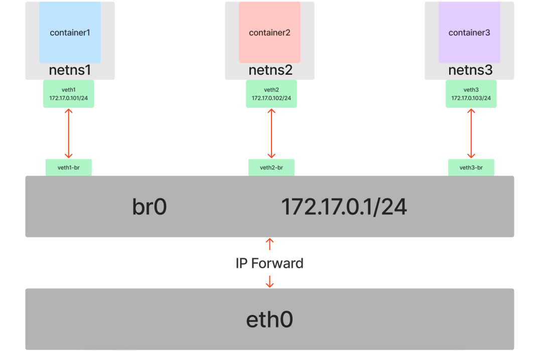
Summary
Docker container network technology is the above Veth+Bridge+route+iptables, but is replaced by Go language to achieve these configurations.
Only when we understand these underlying technologies, we can be more comfortable in dealing with container networking problems.
This article only introduces the default network model of Docker itself, while the CNI container network interface of CNCF (the network model of Kubernetes), Service Mesh + CNI hierarchical SDN will become more and more complex.