In the stand-alone era, the use of a single disk for data storage and read/write resulted in very low I/O performance due to addressing and read/write time consumption, and the storage capacity would also be limited. In addition, a single disk is extremely prone to physical failure, often resulting in data loss. Therefore, people wonder if there is a way to combine multiple independent disks together to form a technical solution to improve data reliability and I/O performance. In this case, RAID technology came into being.
What is RAID?
RAID is the abbreviation of “Redundant Array of Independent Disk”, which means independent redundant disk array in Chinese. The adoption of RAID brings great benefits to the storage system (or the server’s built-in storage), of which increasing the transfer rate and providing fault tolerance are the biggest advantages.
Simply put, RAID is a technology that combines multiple independent hard disks (physical hard disks) in different ways to form a group of hard disks (logical hard disks), thus providing higher storage performance than a single hard disk and providing data backup. Depending on the different combinations of disk displays, RAID can be classified into different levels.
Types of RAID
The level does not represent the level of technology, level 5 is not higher than level 3, level 1 is not lower than level 4, as for the choice of a RAID level product, it depends on the user’s operating environment and application. As for which RAID level product to choose, purely depending on the user’s operating environment (operating environment) and application (application) depends on the level of the high or low does not necessarily relate to.
There is a basic concept in RAID called EDAP (Extended Data Availability and Protection), which emphasizes expandability and fault tolerance mechanisms, and is the focus of various vendors such as Mylex, IBM, HP, Compaq, Adaptec, Infortrend, etc., including the ability to handle the following actions without downtime The following actions can be handled without downtime.
- RAID arrays support automatic detection of failed drives
- RAID arrays support rebuilding data from bad tracks of hard disks
- RAID arrays support non-disruptive hard disk redundancy Hot Spare
- RAID arrays support non-disruptive drive replacement Hot Swap
- RAID arrays support expansion of hard disk capacity, etc.
RAID 0: Bandwidth groups without error control
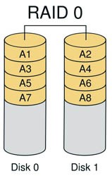
More than two hard drives are required to implement RAID 0. RAID 0 implements striped groups where data is not stored on one hard drive, but is divided into data blocks that are stored on different drives. Because the data is distributed across different drives, the data throughput rate is greatly increased and the load on the drives is more balanced. It is most efficient if just the required data is on different drives. It does not need to calculate checksums and is easy to implement. Its disadvantage is that it does not have data error control, if the data in one drive is incorrect, even if the data on other drives is correct, it will not help. It should not be used for applications that require high data stability. If the user is editing graphics (including animation) and other situations that require larger transfers using RAID 0 is more appropriate. At the same time, RAID can increase the data transfer rate, for example, the files to be read are distributed on two hard disks, which can be read simultaneously. The speed of RAID 0 is the fastest of all levels. But RAID 0 has no redundancy, if one disk (physical) is damaged, all data is unusable.
If two hard disks: 160G + 120G = 240G
RAID 1: Mirror image structure
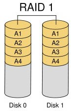
For a device using this RAID 1 architecture, the RAID controller must be able to read to both disks and write to both mirrored disks simultaneously. You can also see in the structure diagram below that there must be two drives. Because it is a mirrored structure you can use mirrors to improve the fault tolerance of the system in case of problems with one set of disks. It is relatively easy to design and implement. Only one piece of data can be read per disk read, which means that the data block transfer rate is the same as the read rate of the individual disks. Because RAID 1 checksums are very complete, they have a significant impact on the processing power of the system. Usually RAID functions are implemented by software, and such an implementation method can greatly affect server efficiency when the server is heavily loaded. When your system needs to be extremely reliable, such as for statistical purposes, then RAID 1 is more appropriate. Moreover, RAID 1 technology supports “hot-swap”, which means that the failed disk can be replaced without power, and the data can be recovered from the mirror disk after the replacement. When the primary hard disk is damaged, the mirror disk can work instead of the primary hard disk. The mirror hard disk is equivalent to a backup disk, so you can imagine that the security of this hard disk mode is very high, RAID 1 data security is the best in all RAID levels. However, its disk utilization is only 50%, which is the lowest of all RAID levels.
If two hard disks: 160G+120G=120G
RAID 2: with Hemming code checksum
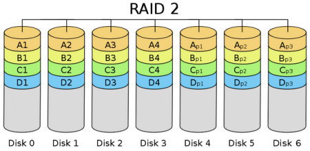
Conceptually, RAID 2 is similar to RAID 3 in that they both strip data across different hard disks in bits or bytes. However, RAID 2 uses certain encoding techniques to provide error checking and recovery. This encoding technique requires multiple disks to hold the inspection and recovery information, making RAID 2 technology more complex to implement. For this reason, it is rarely used in commercial environments. The individual disks on the right side of the diagram above are individual bits of data. The Hemming checksum code, obtained from different bit operations on one piece of data, can be stored on another set of disks, as shown in the diagram below. Due to the characteristics of Hemming code, it can correct the errors in case of data errors to ensure the correct output. Its data transfer rate is quite high, so if you wish to achieve a more desirable speed, it is best to increase the hard disk on which the checksum ECC code is saved, which again is simpler for controller design than RAID 3, 4 or 5. There is no free lunch, and the same is true here. To take advantage of Hemming Code, you must pay the price of data redundancy. The rate of output data is equal to the slowest in the drive group.
RAID 3: Parallel transfer with parity code
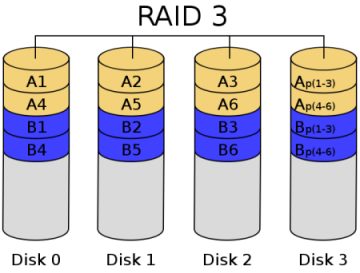
Unlike RAID 2, RAID 3 is a checksum that can only check for errors but not correct them. It accesses data one strip at a time, which increases read and write speeds, and stores data in parallel like RAID 0, but not as fast as RAID 0. The checksum is generated when the data is written and stored on another disk. The user must have more than three drives when implementation is required. The write rate and read rate are both very high, and because there are fewer checksum bits, the computation time is relatively small. Implementing RAID control in software would be very difficult, and the implementation of the controller is not very easy. It is mainly used in applications that require high throughput rates such as graphics (including animation). Unlike RAID 2, RAID 3 uses a single disk to store parity information. If a disk fails, the parity disk and other data disks can regenerate the data. RAID 3 provides good transfer rates for large amounts of sequential data, but for random data, the parity disk can become a bottleneck for write operations. Using separate parity disks to protect data is not as secure as mirroring, but the hard disk utilization is greatly improved to (n-1)/n.
RAID 4: Independent disk structure with parity
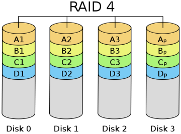
RAID 4 is much like RAID 3, except that it accesses data on a block-by-block basis, that is, disk-by-disk, one disk at a time. You can see it this way on the diagram; RAID 3 is one horizontal strip at a time, while RAID 4 is one vertical strip at a time. Its characteristics are quite similar to RAID 3, but it is much more difficult to recover from a failure than RAID 3. The controller is much more difficult to design, and the efficiency of accessing data is not very good.
RAID 5: Distributed Parity Independent Disk Architecture
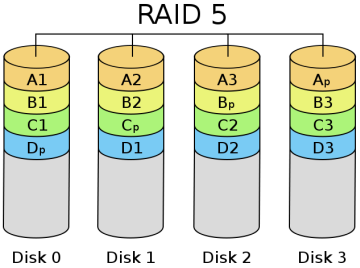
As you can see from its schematic, its parity code exists on all disks, where p0 stands for the parity value of band 0, and the rest means the same. RAID 5 has high read efficiency, average write efficiency, and good block collective access efficiency. Because the parity code is on a different disk, it improves reliability and allows for individual disk errors. RAID 5 also secures data with the parity bits of the data, but instead of storing the parity bits of the data on individual disks, it stores the parity bits of the data segments interactively on individual disks. This way, any hard drive that is corrupted can reconstruct the corrupted data based on the checksum bits on the other hard drives. The hard disk utilization is n-1, but it does not address data transfer parallelism well, and the controller design is quite difficult. the important difference between RAID 3 and RAID 5 is that RAID 3 requires all array disks to be involved for each data transfer. For RAID 5, most data transfers are to one disk and can be performed in parallel. In RAID 5, there is “write loss”, meaning that each write operation will result in four actual read/write operations, with two reads of old data and parity information and two writes of new data and parity information. The biggest advantage of RAID 5 is that if a disk drops, the RAID will work as usual, which is much more fault-tolerant than RAID 0, where every disk must be normal in order to work properly. RAID5 is the most common type of RAID level, and the RAID5 parity bit, or P-bit, is obtained by doing an iso-or (xor) with other striped data. The formula is P=D0xorD1xorD2…xorDn, where p represents the checksum block, Dn represents the corresponding data block, and xor is the mathematical operation symbol iso-or.
RAID6: Two disk structures with parity codes for storage
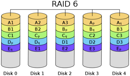
The name is long, but if you see the diagram, you will immediately understand why. Please note that p0 represents the parity value of band 0, while pA represents the parity value of data block A. It is an extension of RAID 5 and is mainly used in situations that require data to be absolutely error-free. Of course, because of the introduction of the second parity value, it requires N+2 disks, while the design of the controller becomes very complex, the write speed is not good, and the time spent to calculate the parity value and verify the correctness of the data is more, resulting in an unnecessary load. I don’t think anyone but the military can afford to use something like this.
RAID 7: Optimized high-speed data transfer disk structure
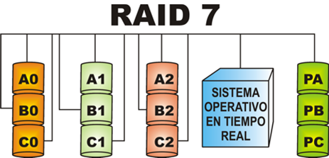
All I/O transfers of RAID 7 are synchronized and can be controlled separately, which improves system parallelism and increases the speed of system access to data; each disk comes with cache memory, and the real-time operating system can use any real-time operating chip to reach the needs of different real-time systems. Allows the use of SNMP protocol for management and monitoring, and can assign separate transmission channels to the checksum area to improve efficiency. Multiple hosts can be connected, and because of the inclusion of cache memory, the access time is almost close to 0 when multiple users access the system. data access efficiency is greatly improved because of the parallel structure. It should be noted that it introduces a cache memory, which has advantages and disadvantages, because once the system loses power, all the data in the cache memory will be lost, so it needs to work with UPS. Of course, something so fast and very expensive.
RAID 10/01: High Reliability and Efficient Disk Architecture
This structure is nothing but a band area structure plus a mirror structure, because the two structures have their own advantages and disadvantages, so they can complement each other to achieve both high efficiency and high speed and can also mirror each other’s purpose. We can understand this new structure by combining the advantages and disadvantages of both structures. The price of this new structure is high and the scalability is not good. It is mainly used in databases that do not have large capacities but require speed and error control.
It can be divided into two combinations: RAID 10 and RAID 01
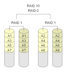
RAID 10 is mirroring before partitioning data. RAID 10 has good read speed and has higher data protection than RAID 0.
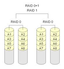
RAID 01 is the opposite of RAID 10, it is partitioned and then mirrored to two sets of hard disks. RAID 01 has faster read and write speeds than RAID 10, but it also has a higher chance of shutting down the entire hard disk group; because if all the hard disks in the same group are destroyed, RAID 01 will stop functioning, while RAID 10 can function normally at the expense of RAID 0. RAID 10 can operate normally at the expense of RAID 0.
RAID 10 cleverly utilizes both the speed of RAID 0 and the protection of RAID 1, but the downside is that it requires more hard drives, as you must have at least four or more even-numbered drives to use it.
RAID 50: Known as distributed parity array striping
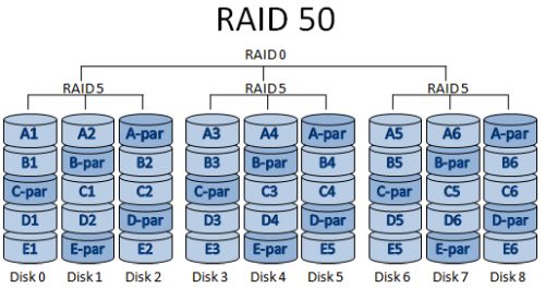
Similar to RAID 10, it has features common to both RAID 5 and RAID 0. It consists of two sets of RAID 5 disks (each with a minimum of three), each set using distributed parity, and the two sets of disks then form a RAID 0 to experiment with data extraction across disks. It consists of two sets of RAID 5 disks (minimum of three in each set), each using distributed parity, and two sets of disks that are then formed into RAID 0 to experiment with extracting data across disks. RAID 50 provides reliable data storage and excellent overall performance, and supports larger volume sizes. Even if two physical disks fail (one in each array), the data can be recovered smoothly.
With a minimum of six drives, RAID 50 is best suited for applications that require highly reliable storage, high read speeds, and high data transfer performance. These applications include transaction processing and office applications with many users accessing small files.
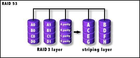
RAID 53: called efficient data transfer disk structure
The structure is implemented as a Level 0 data strip array, where each segment is a RAID 3 array. It has the same redundancy and fault tolerance as RAID 3. This is beneficial for systems that require a RAID 3 configuration with high data transfer rates, but it is expensive and inefficient.
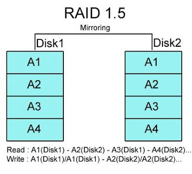
RAID 1.5: A nascent approach to disk arrays
It has the characteristics of RAID 0+1, but the difference is that only 2 disks are required for its implementation. On the surface, after forming RAID 1.5, both disks have the same data. Of course, RAID 1.5 is also an array mode that does not fully utilize disk space, so two 80GB hard disks after forming RAID 1.5 are the same as RAID 1, i.e., only 80GB of actual space is used, and the other 80GB is its backup data. If you separate the two hard drives and run them separately in the original system, it is also unobstructed. However, through practical application, we found that if the two hard disks are run separately, any slight change in their data will cause the array to be reorganized again, and complete data recovery cannot be achieved, but the disk with less data prevails.
JBOD
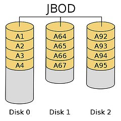
Strictly speaking, JBOD does not belong to the category of RAID, but only merges multiple disk spaces into one large logical disk, which does not have error redundancy mechanism. The data storage mechanism is from the first disk in order to store, that is, the operating system sees a large disk (composed of many small disks). However, if a disk is destroyed, all the data on that disk will not be saved. If the first hard disk is damaged, it is usually impossible to make a rescue (because most file systems store the file table in the front of the disk, i.e. the first one), and losing the file table means losing all the information.
If two hard disks: 160G + 120G = 280G
In practical applications, RAID2~4 does not exist, because RAID5 already covers the required functions. Therefore, RAID2~4 are currently only available in the research field, while in practical applications, RAID 0, 1, 0+1, 5 or RAID6 are the main ones. However, for us ordinary users, the most used ones are RAID 0, 1, 0+1 and RAID 5.
Hard RAID Full Soft RAID Half Soft RAID
Depending on the prior method, there are three types of RAID: software RAID (soft RAID), hardware RAID (hard RAID), and hardware-assisted RAID (semi-soft, semi-hard).
Hardware RAID (hardware disk array)
The simple fact is that all RAID functions are achieved by using hardware is hard RAID, for example: various RAID cards, and motherboard integration can do RAID are hard RAID.
So hard RAID is a special RAID controller (RAID card) that connects the hard disks to the computer, and the RAID controller is responsible for configuring all RAID member disks into a virtual RAID volume. For the operating system, it can only recognize the virtual disks configured by the RAID controller, but not the individual member disks that make up the RAID.
Hard RAID is fully equipped with its own RAID control/processing and I/O processing chips, and even has Array Buffer, which has the most advantages in terms of CPU usage and overall performance.
Advantages.
- CPU usage and overall performance is the most advantageous of the three types
- Can be rebuilt if a hard drive is lost, and can be replaced if the RAID card is damaged
Disadvantages.
- Equipment cost is the highest of the three types
- Requires a certain level of technical knowledge
Software RAID (Software Disk Array)
On the other hand, soft RAID is achieved by using the operating system to perform RAID functions, such as RAID5 with three hard disks under Linux operating system, which means that the RAID controller (known as RAID Co-Processor) and I/O chips are not used, and are implemented directly through the software layer. All functions are performed by the operating system (OS) and CPU, which is conceivably the least efficient type of RAID.
Unlike hard RAID, the individual member disks of a soft RAID are visible to the OS, but the OS does not present the individual member disks to the user, but only the virtual RAID volume configured through the software layer, allowing the user to use the RAID volume as if it were a normal disk.
Advantages.
- Low cost, requires only motherboard support, and does not require any disk array card
- Simple to implement
Disadvantages.
- More CPU resources are consumed for RAID computing, which leads to heat and other problems, and is not stable enough.
- Dependent on the operating system, and the operating system 。。。。
- If the motherboard is damaged, it may be difficult to purchase the same motherboard to rebuild RAID
Hardware-Assisted RAID (HADR)
In contrast to hard RAID and full soft RAID, semi-soft RAID requires a RAID card and a driver provided by the vendor. However, semi-soft and semi-hard RAID lacks its own I/O processing chip, so it is still up to the CPU and driver to do this work. Moreover, the RAID controller/processing chip used in semi-soft and semi-hard RAID is generally weak and cannot support high RAID levels. This type of RAID is easier to migrate to other computers.
Advantages.
- Improved performance and stability over soft RAID
- Easier to migrate to other computers
Disadvantages.
- Not as good as the top, not as good as the bottom
Remarks: When using hard disk group Raid, it is better to buy different brands or different batches of hard disks of the same brand, because there is a very high probability that the same brand and batch of hard disks will be damaged at the same time.