There are various network solutions for containers, and it is obviously impractical to adapt every network implementation supported, and CNI was invented to be compatible with multiple network solutions.CNI stands for Container Network Interface, which is a standard common interface to connect container management system and network plugins.
In simple terms, container runtime provides network namespace for containers, network plug-in is responsible for inserting network interface into the network namespace and doing some necessary configuration in the host, and finally configuring IP and routing for the interface in the namespace.
So the main job of the network plug-in is to provide a network environment for the container, including setting the ip address for the pod and configuring the route to ensure the smooth flow of the network within the cluster. Currently the most popular network plugins are Flannel and Calico.
Flannel
Flannel primarily provides an overlay network within a cluster and supports three backend implementations: UDP mode, VXLAN mode, and host-gw mode.
UDP Mode
UDP mode, one of the first supported by the Flannel project, is also one of the worst performing. This mode provides a three-layer overlay network, i.e., it first encapsulates the outgoing IP packet in UDP, then decapsulates it at the receiving end to get the original IP packet, which is then forwarded to the destination container. The working principle is shown in the figure below.
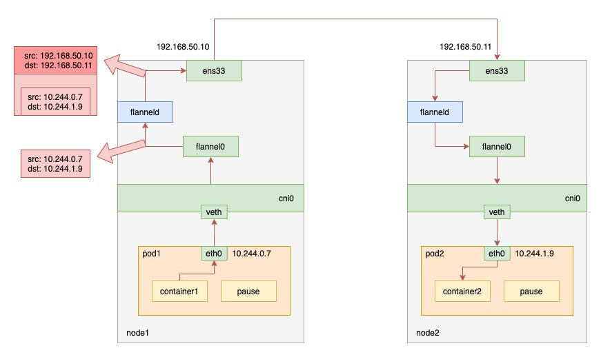
When pod1 on node1 requests pod2 on node2, the traffic goes as follows.
- the process in pod1 initiates the request and sends an IP packet.
- the IP packet enters the cni0 bridge based on the veth device pair in pod1.
- since the destination ip of the IP packet is not on node1, it enters flannel0 according to the routing rules created by the flannel on the node. 4.
- at this point the flanneld process receives the packet, flanneld determines which node the packet should be on and encapsulates it in a UDP packet
- finally send it to node2 through the gateway on node1.
flannel0 is a TUN device (Tunnel device). In Linux, a TUN device is a virtual network device that works at three layers (Network Layer).The function of the TUN device: to pass IP packets between the OS kernel and the user application.
As you can see, the reason for the poor performance of this mode is that the entire packet UDP encapsulation process is done by the flanneld program, i.e. the user state, and this brings about a kernel-to-user state transition and a user-to-kernel state transition. The cost in context switching and user state operation is actually higher, and UDP mode brings additional performance consumption because of packet encapsulation and unpacketization.
VXLAN mode
VXLAN, or Virtual Extensible LAN, is a network virtualization technology that is supported by the Linux kernel itself. By taking advantage of this feature of the Linux kernel, the ability to encapsulate and decapsulate in the kernel state can also be implemented to build overlay networks. The working principle is shown in the following figure.
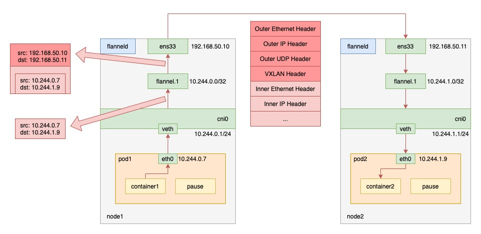
VXLAN mode flannel creates a VTEP (Virtual Tunnel End Point) device called flannel.1 on the node, which, like UDP mode, encapsulates Layer 2 data frames in UDP packets and forwards them out. Unlike UDP mode, the encapsulation process is done in the kernel state.
When pod1 on node1 requests pod2 on node2, the traffic goes as follows.
- the process in pod1 initiates the request and sends an IP packet.
- the IP packet enters the cni0 bridge based on the veth device pair in pod1.
- since the destination ip of the IP packet is not on node1, it enters flannel.1 according to the routing rules created by the flannel on the node.
- flannel.1 encapsulates the original IP packet with a destination MAC address into a layer 2 data frame; the kernel then encapsulates the data frame into a UDP packet;
- finally, through the gateway on node1, to node2.
Packet capture verification
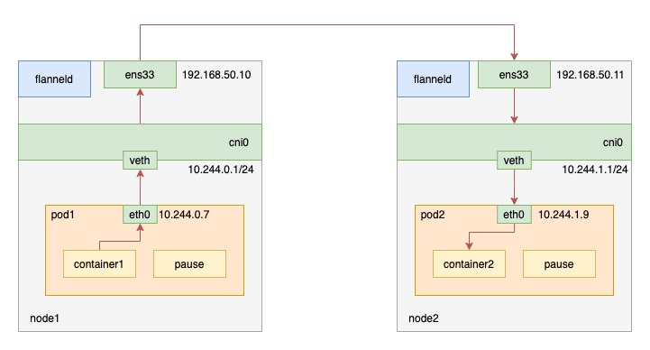
Deploy a nginx pod1 on node1 and a nginx pod2 on node2. Then curl the pod2 container on port 80 in the pod1 container.
The cluster network environment is as follows.
The routing information on node1 is as follows.
|
|
Packet capture for NIC ens33 of node1.
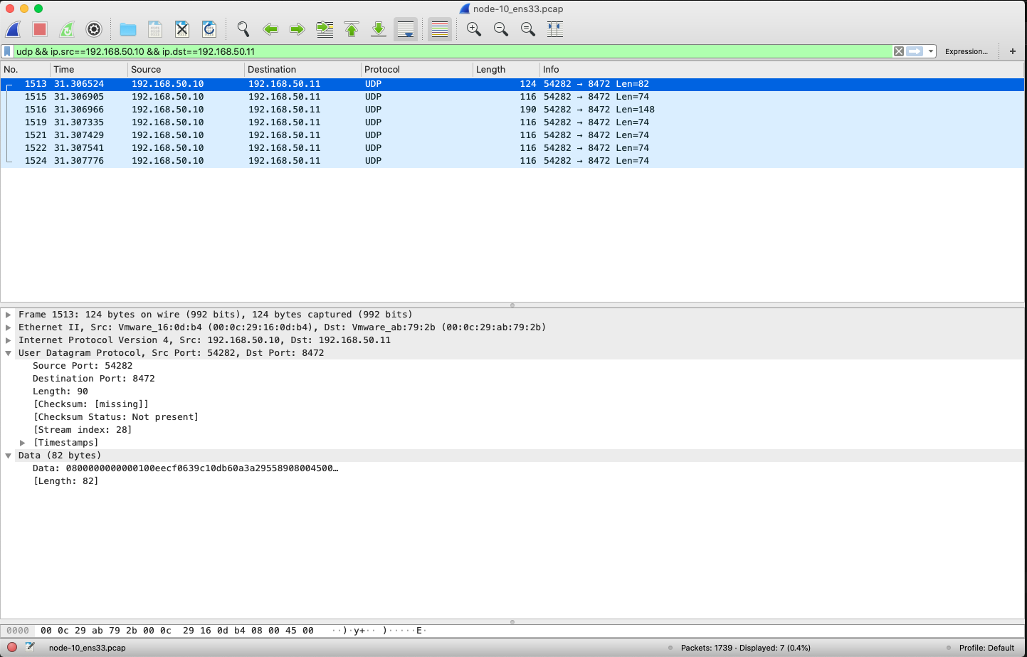
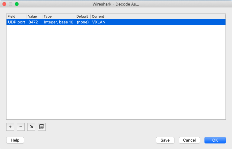
We can only see UDP packets with source ip node1 ip and destination ip node2 ip. Since flannel.1 has a layer of UDP packets, here we set up Wireshark to parse the UDP packets into VxLAN format (port 8472) by Analyze->Decode As.
Then take a look at the packets received on the node1 NIC.
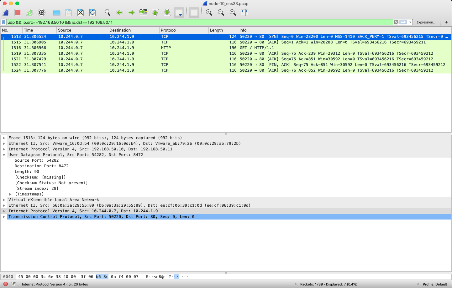
You can see that the source ip is pod1 ip, the destination ip is pod2 ip, and the IP packet is encapsulated in a UDP packet.
host-gw mode
The last host-gw mode is a pure Layer 3 network solution. It works by setting the “next hop” of each Flannel subnet to the IP address of the host corresponding to that subnet, which acts as the “gateway” in the container communication path. This allows IP packets to reach the destination host through the Layer 2 network, and because of this, the host-gw mode requires that the network between the cluster hosts be Layer 2 connected, as shown in the figure below.
The routing information on the host is set by flanneld, and since the flannel subnet and host information is stored in etcd, flanneld only needs to watch for changes in this data and update the routing table in real time. In this mode, the process of container communication eliminates the performance loss caused by additional packets and unpackets.
When pod1 on node1 requests pod2 on node2, the traffic goes as follows.
- the process in pod1 initiates the request and sends out IP packets, which are encapsulated into frames from the network layer into the link layer.
- the data frames arrive on Node 2 from Node 1 through the host’s Layer 2 network according to the routing rules on the host.
Calico
Instead of using CNI’s bridge mode, Calico treats the nodes as border routers, forming a fully connected network that exchanges routes via the BGP protocol. Therefore, Calico’s CNI plug-in also requires a routing rule on the host for each container’s Veth Pair device to receive incoming IP packets.
Calico’s components:
- CNI plug-in: the part of Calico that interfaces with Kubernetes
- Felix: responsible for inserting routing rules on the host (i.e., writing to the Linux kernel’s FIB forwarding information base) and maintaining the network devices required by Calico, etc.
- BIRD (BGP Route Reflector): is a client of BGP and is specifically responsible for distributing routing rule information in the cluster.
All three components are installed through a DaemonSet; the CNI plugin is installed through initContainer; and Felix and BIRD are two containers of the same pod.
How it works
Calico uses BGP, a protocol that enables node routing information sharing in large-scale networks. The full name is Border Gateway Protocol, or: Border Gateway Protocol. It is a centralless routing protocol that is natively supported by the Linux kernel and is designed to maintain routing information between different “autonomous systems” in a large-scale data center.
Since it does not use CNI bridges, Calico’s CNI plug-in requires a Veth Pair device for each container, one end of which is placed on the host, and a routing rule on the host for each container’s Veth Pair device to receive incoming IP packets. This is shown in the figure below.
You can check the node connectivity of node1 using calicoctl.
|
|
You can see that there are 3 nodes on the entire calico cluster, node1 and the other two nodes are in a connected state with the mode “Node-to-Node Mesh”. Then look at the routing information on node1 as follows.
|
|
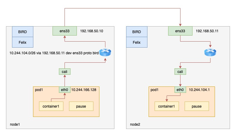
The routing rule in #2 indicates that packets from the 10.244.104.0/26 network segment are sent from the ens33 device to the gateway 192.168.50.11 via the bird protocol. this also defines the destination ip as the direction of the pod request on node2. Routing rule #3 is similar.
packet capture verification
As above, an http request is sent from pod1 on node1 to pod2 on node2.
The cluster network environment is as follows.
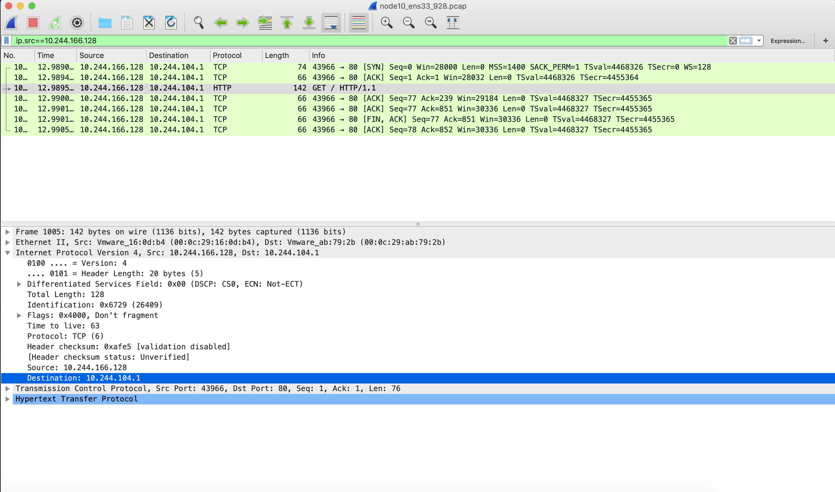
Packet capture for NIC ens33 of node1.
IPIP mode
IPIP mode is used to solve the problem that two nodes are not on the same subnet. Just set the environment variable CALICO_IPV4POOL_IPIP to “Always” for the daemonset named calico-node. As follows.
IPIP mode calico uses the tunl0 device, which is an IP tunneling device. after the IP packet enters tunl0, the kernel encapsulates the original IP packet directly in the IP packet of the host; the destination address of the encapsulated IP packet is the next hop address, which is the IP address of node2. Since the hosts have already configured Layer 3 forwarding between them using a router, this IP packet can pass through the router after leaving node 1 and eventually be sent to node 2. This is shown in the figure below.
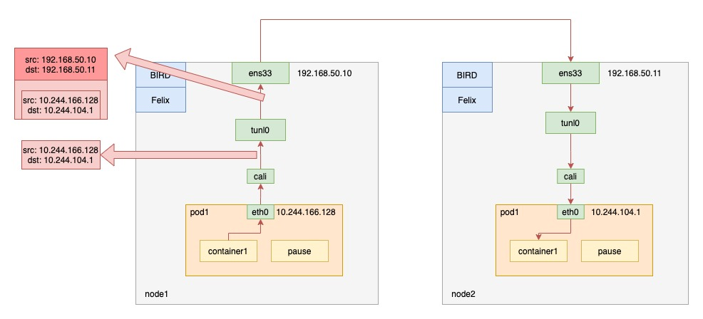
Since the cluster’s network performance is affected by the extra packet sealing and unpacking process of Calico in IPIP mode, it is recommended not to use IPIP mode when the cluster’s Layer 2 network is through.
Take a look at the routing information on node1.
|
|
You can see that, unlike before, the packet with destination IP Pod on node2 is sent to gateway 192.168.50.11 via tunl0.
Packet capture verification
Send an http request from pod1 on node1 to pod2 on node2.
The cluster network environment is as follows.
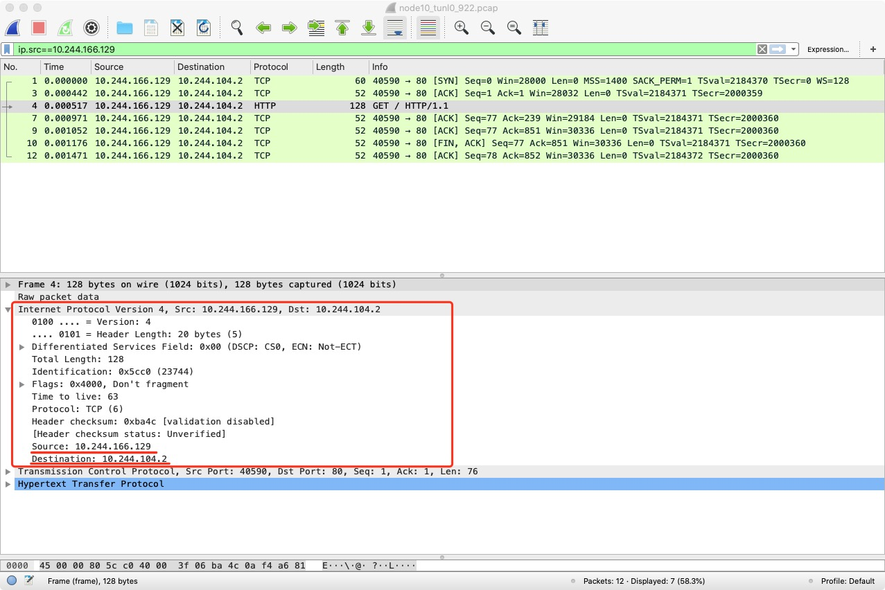
Packet capture for tunl0 devices.
Packet capture for node1 NIC ens33.
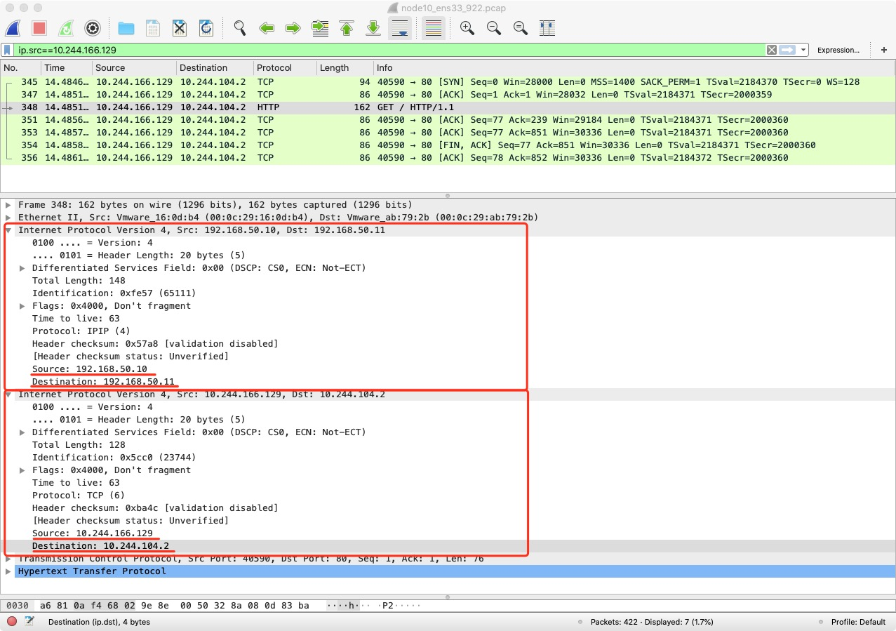
You can see that the IP packet is encapsulated into another IP packet in the tunl0 device with the destination IP of node2 and the source IP of node1.
Summary
This article analyzes the working principle of Flannel and Calico, which are the two most common ones in the community, and analyzes the direction of network packets by capturing packets for the scenario of communication between pods of different nodes in the cluster.
Flannel mainly provides an overlay network solution; UDP mode is gradually abandoned by the community because its packet unpacking process involves multiple context switches, resulting in poor performance; VXLAN mode has a much better performance than UDP because its packet unpacking process is in the kernel state, and is the most frequently used mode; host-gw mode does not involve packet unpacking, so its performance is relatively high, but requires Layer 2 interoperability between nodes.
Calico mainly uses BGP protocol to exchange routes without cni0 bridge. When the Layer 2 network is not available, IPIP mode can be used, but the performance is relatively weak due to the packet unpacking process, which is comparable to Flannel’s VXLAN mode.