Why VLANs are needed
What is VLAN
A LAN can be a network of a few home computers or a corporate network of hundreds of computers, and a VLAN (Virtual LAN) refers specifically to a network that is segmented using routers - that is, a broadcast domain.
Let’s review the concept of a broadcast domain here.
The Broadcast Domain is the range to which a broadcast frame (with a destination MAC address of all 1s) can pass, i.e. the range to which it can communicate directly. Strictly speaking, it is not only broadcast frames, but Multicast frames and Unknown Unicast frames can also travel unimpeded in the same broadcast domain.
Originally, a Layer 2 switch could only build a single broadcast domain, but with the VLAN feature, it can partition the network into multiple broadcast domains.
When the broadcast domain is not split
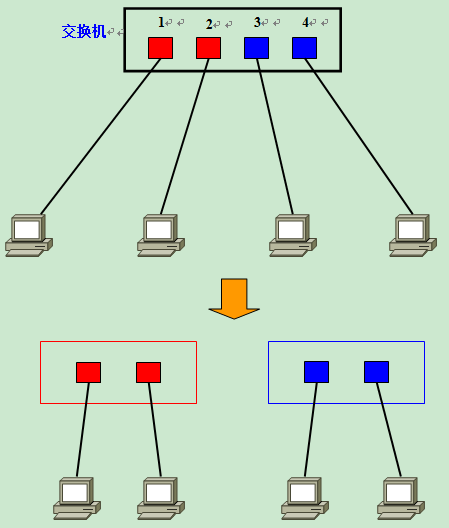
So, why do you need to split the broadcast domain? That is because, if there is only one broadcast domain, it may affect the overall transmission performance of the network. The figure below shows a network consisting of five Layer 2 switches (switches 1 to 5) connected with a large number of clients.
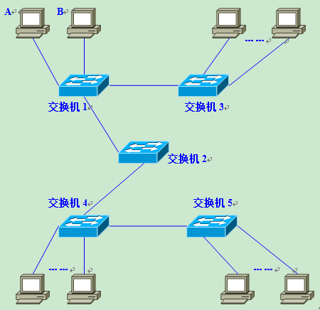
Suppose at this point, Computer A needs to communicate with Computer B. In Ethernet-based communication, the destination MAC address must be specified in the data frame in order to communicate properly, so Computer A must first broadcast an ARP Request message to try to obtain Computer B’s MAC address.
After switch 1 receives the broadcast frame (ARP Request), it will forward it to all ports except the receiving port, which is Flooding. Next, switch 2 receives the broadcast frame and Floods it as well. switches 3, 4, and 5 also Flood. eventually the ARP request is forwarded to all clients in the same network.
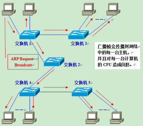
Please note that this ARP request was originally sent to get the MAC address of computer B. In other words: as long as computer B receives it, everything is fine. But in fact, the data frame is transmitted all over the network, causing all computers to receive it. In this way, on the one hand, the broadcast message consumes the overall bandwidth of the network, and on the other hand, the computer receiving the broadcast message consumes some CPU time to process it. This results in a significant unnecessary consumption of network bandwidth and CPU computing power.
Are broadcast messages that frequent?
As you read this, you may ask: Are broadcast messages really that frequent?
The answer is: Yes! Broadcast frames can actually occur very frequently. When communicating using the TCP/IP stack, in addition to the ARP that appeared earlier, there are many other types of broadcast messages that may need to be sent out such as DHCP, RIP, and so on.
The following are some common broadcast communications.
- ARP request: Establishes a mapping relationship between IP address and MAC address. It is issued when communication with other hosts is needed.
- RIP: A routing protocol. Routers broadcast routing information to other routers in the vicinity every 30 seconds. routing protocols other than RIP use multicast to transmit routing information, which is also forwarded by the switch (Flooding)
- DHCP: A protocol used to automatically set IP addresses. When a client requests a DHCP server to assign an IP address, it must send a DHCP broadcast.
- NetBEUI: A network protocol used under Windows.
- IPX: Network protocol used by NovellNetware.
- Apple Talk: A network protocol used by Apple’s Macintosh computers.
If there is only one broadcast domain for the entire network, then once a broadcast message is sent, it travels throughout the network and places an additional burden on the hosts in the network. Therefore, when designing a LAN, attention needs to be paid to how you can effectively split the broadcast domain.
Partitioning of broadcast domains and the need for VLANs
When splitting broadcast domains, it is generally necessary to use a router. When a router is used, the network interface (LAN Interface) on the router can be used as unit to divide the broadcast domain.
However, usually there are not too many network interfaces on the router, and the number of them is mostly around 1 to 4. With the popularity of broadband connections, broadband routers (or IP sharers) have become more common, but it should be noted that they come with multiple (usually about 4) network interfaces on the LAN side of the connection, but that is actually the router built-in switch and does not divide the broadcast domain.
In addition, if you use a router to split the broadcast domain, the number of splits depends entirely on the number of network interfaces on the router, making it impossible for users to freely split the broadcast domain according to their actual needs.
In contrast to routers, Layer 2 switches generally have multiple network interfaces. Therefore, if you can use it to split broadcast domains, you will undoubtedly have much more flexibility in using it.
The technology used to split broadcast domains on Layer 2 switches is VLAN. By using VLANs, we can freely design the composition of the broadcast domain and increase the freedom of network design.
Mechanisms for implementing VLANs
Mechanisms for Implementing VLANs
Having understood “why VLANs are needed”, let’s look at how switches use VLANs to segment broadcast domains.
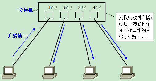
First, on a Layer 2 switch without any VLANs, any broadcast frames will be forwarded to all ports except the receiving port (Flooding). For example, after computer A sends a broadcast message, it is forwarded to ports 2, 3, and 4.
At this point, if two VLANs are generated on the switch, red and blue; ports 1 and 2 are in the red VLAN and ports 3 and 4 are in the blue VLAN, and if a broadcast frame is sent from A, the switch will only forward it to other ports in the same VLAN-that is, port 2 in the red VLAN-and not forward it to port 2 in the blue VLAN. If a broadcast frame is sent from A, the switch will forward it to another port in the same VLAN - that is, port 2 in the same red VLAN - and not to a port in the blue VLAN.
Similarly, when C sends a broadcast message, it will only be forwarded to other ports belonging to the blue VLAN, not to ports belonging to the red VLAN.
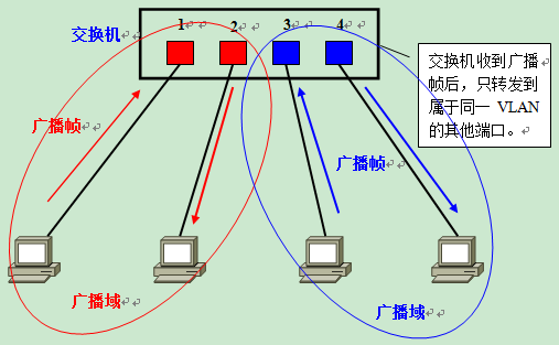
In this way, VLANs are partitioned into broadcast domains by limiting the range of broadcast frames to be forwarded. The different VLANs are identified in red and blue in the figure above for illustration purposes, but in practice they are distinguished by VLAN ID.
Visual description of VLANs
For a more intuitive description of VLANs, we can think of it as a switch that is logically partitioned into several switches. Generating red and blue VLANs on a switch can also be thought of as replacing one switch with two virtual switches, one red and one blue. When generating new VLANs in addition to the red and blue VLANs, it can be imagined as adding another new switch.
However, the switches on the logical generated by the VLAN are not communicating with each other. Therefore, after setting up VLANs on a switch, it is impossible to communicate between VLANs if no other processing is done. The fact that you are obviously connected to the same switch, but you just can’t communicate - this fact may be hard to accept. But it is both the feature that makes VLANs convenient and easy to use, and the reason that makes them so difficult to understand.
What to do when you need to communicate between VLANs
So what happens when we need to communicate between different VLANs? Please recall again: a VLAN is a broadcast domain. Usually two broadcast domains are connected by routers, and packets to and from broadcast domains are relayed by routers. Therefore, inter-VLAN communication also requires routers to provide trunking services, which is called Inter-VLAN routing.
For inter-VLAN routing, you can use a normal router or a Layer 3 switch. Here I hope you first remember that the routing function is needed when different VLANs communicate with each other.
Access Link of the VLAN
Port type of the switch
The ports of the switch, which can be divided into the following two types.
- Access Link (Access Link)
- Trunk Link (Aggregation Link)
Access Link
An access link, a port that belongs to only one VLAN and forwards data frames to that VLAN only. In most cases, the access link is connected to a client machine.
The usual order of setting up VLANs is
- Generate VLANs
- Set the access link (determine which VLAN each port belongs to)
There are two ways to set up access links.
- Static VLAN: fixed in advance
- Dynamic VLAN: ∂ dynamically change the settings according to the connected computers
Static VLANs - PortBased
Static VLANs are also known as PortBased VLANs (PortBased VLANs). As the name implies, it is a setting method that explicitly specifies which VLAN each port belongs to.
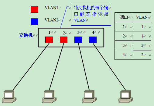
Because of the need to specify ports one by one, the setup operation becomes cumbersome when the number of computers in the network exceeds a certain number (e.g., hundreds). Moreover, each time a client changes its port, it must also change the settings of the VLAN to which the port belongs - clearly not suitable for networks that require frequent topology changes.
Dynamic VLANs
Dynamic VLANs, on the other hand, change the VLAN to which a port belongs at any time, depending on the computers connected to each port, thus avoiding the above-mentioned operations such as changing settings. Dynamic VLANs can be broadly classified into three categories.
- MAC address-based VLAN (MAC Based VLAN)
- Subnet Based VLAN (Subnet Based VLAN)
- User Based VLAN (User Based VLAN)
The difference lies mainly in which layer of the OSI reference model determines which VLAN a port belongs to.
MAC address-based VLAN
MAC address-based VLAN determines the port’s affiliation by querying and recording the MAC address of the computer’s network card connected to the port. Assuming that a MAC address A is set by the switch to belong to VLAN 10, the port will be assigned to VLAN 10 regardless of which port the computer with MAC address A is connected to.
- When the computer is connected to port 1, port 1 belongs to VLAN 10
- When the computer is connected to port 2, port 2 belongs to VLAN 10
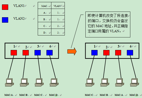
Since it is based on the MAC address to determine the VLAN to which it belongs, it can be interpreted as a way to set the access link at the second layer of OSI.
However, for VLANs based on MAC addresses, the MAC addresses of all connected computers must be investigated and logged in when setting. And if the computers swap NICs, the settings still need to be changed.
IP address-based VLANs
Subnet-based VLAN determines the VLAN to which a port belongs by the IP address of the connected computer. Unlike MAC address-based VLANs, even if a computer’s MAC address changes due to a switch of NICs or other reasons, it can still join the original VLAN as long as its IP address remains the same.
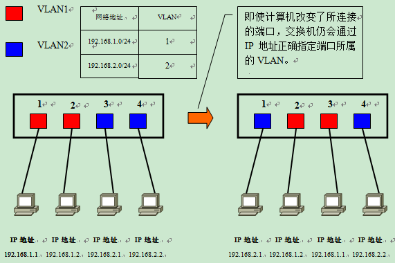
Therefore, it is possible to change the network structure more easily than MAC address-based VLANs. IP addresses are information at layer 3 in the OSI reference model, so we can understand that subnet-based VLANs are a method of setting access links at layer 3 of the OSI.
User-based VLANs, on the other hand, determine which VLAN the port belongs to based on the user currently logged in on the computer connected to each port of the switch. here, the user identification information is generally the user logged in by the computer’s operating system, which can be, for example, the user name used in the Windows domain. This user name information, belongs to OSI layer 4 and above.
In general, the higher the level of information in the OSI utilized in determining the VLAN to which a port belongs, the more suitable it is for building a flexible and versatile network.
Summary of access links
In summary, there are two techniques for setting access links, static VLANs and dynamic VLANs, of which dynamic VLANs can be further subdivided into several subcategories.
Among them, subnet-based VLANs and user-based VLANs are likely to be implemented by network equipment vendors using unique protocols, and interconnection between devices from different vendors may have compatibility issues; therefore, when selecting a switch, care must be taken to confirm in advance.
The following table summarizes the information about static VLANs and dynamic VLANs.
| Kinds | Explanation | |
|---|---|---|
| Static VLANs (port-based VLANs) | assign each port of the switch to a fixed VLAN | |
| Dynamic VLANs | MAC address-based VLANs | are set based on the MAC address of the computer connected to each port |
| Subnet-based VLANs | based on the IP address of the computer attached to each port | |
| User-based VLAN | based on the logged-in user on the computer connected to the port |
VLAN aggregation link Trunk Link
When you need to set up VLANs that span multiple switches
Up to this point, we have learned about setting up VLANs using a single switch. What about when you need to set up VLANs that span multiple switches?
When planning an enterprise network, it is likely that users belonging to the same department will be scattered on different floors of the same building, and it may be necessary to consider how to set up VLANs across multiple switches. Suppose there is a network as shown in the figure below, and it is necessary to set A, C and B, D on different floors as the same VLAN.
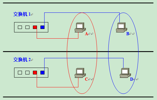
The most critical thing at this point is how to connect switch 1 and switch 2? The easiest way, naturally, is to set up a dedicated red and blue VLAN interface on each of Switch 1 and Switch 2 and interconnect them.
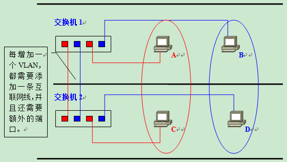
However, this approach is not good in terms of scalability and management efficiency. For example, when a new VLAN is created on top of the existing network, new network cables need to be connected between switches in order to make this VLAN interoperable. The vertical wiring between floors of a building is troublesome and generally cannot be done by the basic management at will. Moreover, the more VLANs there are, the more ports are required for interconnection between floors (strictly speaking, between switches), and the inefficient use of switch ports is a waste of resources and limits the expansion of the network.
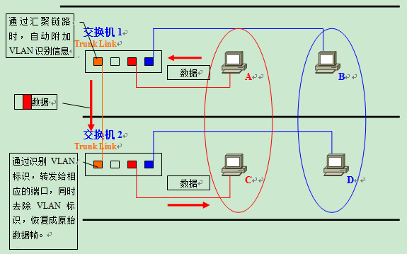
In order to avoid this inefficient connection, people find a way to make the interconnection between switches to a single network cable, which is used Trunk Link.
What is a Trunk link?
A Trunk Link is a port that is capable of forwarding traffic from multiple different VLANs.
The data frames circulating on a trunk link are tagged with special information that identifies which VLAN they belong to.
Now let’s go back and consider what would have happened if that network had used aggregation links. The user would simply set the ports on the interconnect between the switches to aggregated links. The network cable used at this point is still a normal UTP cable and not any other special cabling. The illustration shows an inter-switch interconnect, so it needs to be connected with crossover cable.
Next, let’s look specifically at how the aggregation link is implemented across the VLANs between the switches.
When the data frame sent by A arrives at switch 2 via the aggregation link from switch 1, a tag indicating that it belongs to a red VLAN is appended to the data frame.
After receiving the data frame, Switch 2 finds that this data frame belongs to the red VLAN after checking the VLAN identifier, so Remove the tag and forward the recovered data frame to other ports belonging to the red VLAN only as needed. At this point, the forwarding means that after confirming the target MAC address and comparing it with the MAC address list only the ports connected to the target MAC address are forwarded. Only if the data frame is a broadcast frame, a multicast frame, or a frame with an unknown destination, it will be forwarded to all ports belonging to the red VLAN.
The same is true for data frames sent by the blue VLAN.
The VLAN identification information that is appended when passing through the aggregation link may support the standard IEEE 802.1Q protocol, or it may be ISL (Inter Switch Link), which is unique to Cisco products. If the switch supports these specifications, then users will be able to efficiently construct VLANs across multiple switches.
In addition, the aggregation link is naturally heavily loaded with data from multiple VLANs circulating on it. Therefore, when setting up an aggregation link, one prerequisite is that it must support a transmission speed of 100Mbps or more.
By default, the aggregation link forwards data from all the VLANs present on the switch. To reduce the load on the switch and to reduce the waste of bandwidth, we can limit the VLANs that can be interconnected via the aggregation link through user settings, since in practice it is likely that not all VLANs need to be forwarded.
The details of IEEE 802.1Q and ISL will be discussed in the next section.
Aggregation method for VLANs
Aggregation method
VLANs across multiple switches can be constructed by attaching VLAN information to data frames on the aggregation links of the switches. the most representative methods of attaching VLAN information are
- IEEE 802.1Q
- ISL
IEEE 802.1Q
IEEE 802.1Q, commonly known as “Dot One Q”, is an IEEE certified protocol for attaching VLAN identification information to data frames.
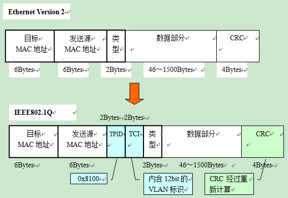
Here, please recall the standard format of Ethernet data frames.
The VLAN identification information appended by IEEE 802.1Q is located between the “Sending Source MAC Address” and the “Type Field” in the data frame. The content is
- 2 bytes of the TPID (Tag Protocol IDentifier)
- 2 bytes of TCI (Tag Control Information), for a total of 4 bytes.
When 4 bytes are added to the data frame, then the CRC value will naturally change as well. In this case, the CRC on the data frame is the value obtained by recalculating the entire data frame including TPID and TCI after inserting them.
The TPID and TCI are removed when the data frame leaves the aggregation link, and a CRC recalculation is performed at that time.
The TPID field is located in the same position in an Ethernet message as the Protocol Type field in a message without a VLAN Tag.
- The value of TPID is fixed at 0x8100, which identifies the 802.1Q type carried by the network frame, by which the switch determines that IEEE 802.1Q-based VLAN information is appended within the data frame.
- And essentially the VLAN ID, which is a 12-bit element in the TCI. Since there are 12 bits in total, up to 4096 VLANs can be identified.
The VLAN information attached based on IEEE 802.1Q is like a Tag attached to the item being delivered. Therefore, it is also called Tagging VLAN.
ISL (Inter Switch Link)
ISL is a protocol supported by Cisco products for attaching VLAN information to aggregation links similar to IEEE 802.1Q.
With ISL, an ISL Header of 26 bytes is appended to the header of each data frame, and a 4-byte CRC value is added to the end of the frame by calculating the entire data frame including the ISL Header. In other words, a total of 30 bytes of information is added.
In an environment where ISL is used, when the data frame leaves the aggregation link, it is simply removed from the ISL packet header and the new CRC. Since the original data frame and its CRC are kept intact, there is no need to recalculate the CRC.
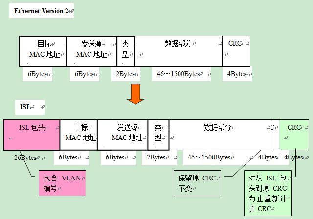
ISL has the effect of wrapping the entire original data frame with an ISL packet header and a new CRC, hence the term Encapsulated VLAN.
It should be noted that neither the Tagging VLAN of IEEE802.1Q, nor the Encapsulated VLAN of ISL is a very strict term. In different books and reference materials, the above terms may be mixed, so you need to pay extra attention when learning.
And because ISL is a unique Cisco protocol, so it can only be used for interconnection between Cisco network devices.
Inter-VLAN Routing
The need for inter-VLAN routing
Based on what we have learned so far, we already know that two computers cannot communicate directly with each other even if they are connected to the same switch, as long as they belong to different VLANs. The next thing we will learn is how to route between different VLANs so that hosts belonging to different VLANs can communicate with each other.
First, let’s review why different VLANs can’t communicate with each other without routing. To communicate within a LAN, the MAC address of the communication destination must be specified in the data frame header. And to get the MAC address, ARP is used under TCP/IP protocol. The method of resolving MAC address by ARP is through broadcast. In other words, if a broadcast message cannot be reached, then there is no way to resolve the MAC address, i.e., no direct communication is possible.
Computers belong to different VLANs, which means they belong to different broadcast domains, and naturally cannot receive each other’s broadcast messages. Therefore, computers belonging to different VLANs cannot communicate with each other directly. In order to be able to communicate between VLANs, information from the higher layer of the OSI reference model - the network layer (IP address) - needs to be used for routing.
The routing function, in general, is mainly provided by routers. But in today’s LANs, we also often use a switch with routing capabilities - a Layer 3 Switch. Let’s take a look at what happens when routing between VLANs using a router and a Layer 3 Switch, respectively.
Inter-VLAN routing with a router
When using a router for inter-VLAN routing, similar to when building a VLAN across multiple switches, we still encounter the problem of “how to connect the router to the switch”. There are two general ways to wire a router to a switch.
- Connect the router to each VLAN on the switch separately
- No matter how many VLANs there are, the router and the switch are connected with only one network cable.
The easiest way to think of is “connect the router to the switch with a separate cable for each VLAN”. Set each port on the switch for interconnection with the router as Access Link, and then interconnect it with a separate port on the router using a network cable. As shown in the figure below.
- 2 VLANs on the switch, then 2 ports need to be reserved on the switch for interconnection with the router.
- The same 2 ports are required on the router; the two are connected separately with 2 network cables.
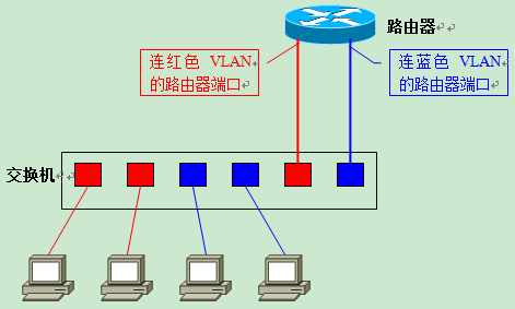
If this approach is used, one should have no trouble imagining that its scalability is problematic. Each new VLAN requires the consumption of the router’s ports and access links on the switch, and a new network cable needs to be laid. Routers, on the other hand, usually do not come with too many LAN interfaces. When a new VLAN is created, the router must be upgraded to a high-end product with multiple LAN interfaces in order to correspond to the ports required for the additional VLAN.
What about the second option, “use only one cable to connect the router to the switch, regardless of the number of VLANs”? When using a network cable to connect the router to the switch, inter-VLAN routing, the need to use the aggregation link.
The process is as follows: First, the switch port used to connect the router is set as a Trunk Link, and the port on the router must also support the Trunk Link. The protocols used by both sides for the aggregation link must naturally be the same. Next, a “Sub Interface” (Sub Interface) is defined on the router for each VLAN. Although there is only one physical port that is actually connected to the switch, in theory we can split it into multiple virtual ports.
VLANs logically divide the switch into multiple units, so the routers used for inter-VLAN routing must also have virtual interfaces that correspond to each VLAN.
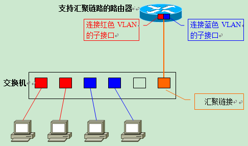
With this method, even if a new VLAN is created on the switch later, only one network cable is needed to connect the switch to the router. The user only needs to set up a new sub-interface on the router that corresponds to the new VLAN. Compared with the previous method, it is much more scalable, and there is no need to worry about upgrading routers with insufficient LAN interfaces or rewiring.
Communication within the same VLAN
Next, let’s move on to learn how inter-VLAN routing works when using aggregation links to connect the switch to the router. As shown in the figure below, IP addresses are set for each computer and the router’s sub-interfaces.
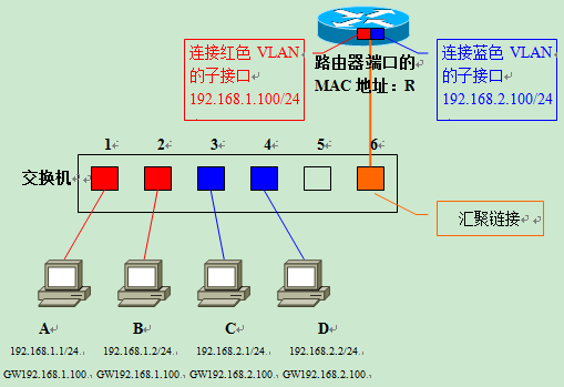
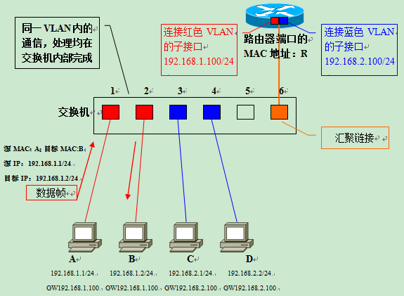
The network address of the red VLAN (VLAN ID=1) is 192.168.1.0/24, and the network address of the blue VLAN (VLAN ID=2) is 192.168.2.0/24. The MAC addresses of each computer are A/B/C/D, and the MAC address of the router’s aggregation link port is R. The switch generates the following MAC address list by learning the MAC addresses of the computers connected to each port. The switch generates the following MAC address list by learning the MAC addresses of the computers connected to each port.
| Port | MAC Address | VLAN |
|---|---|---|
| 1 | A | 1 |
| 2 | B | 1 |
| 3 | C | 2 |
| 4 | D | 2 |
| 5 | - | - |
| 6 | R | Trunk |
First, consider the situation when computer A communicates with computer B in the same VLAN.
Computer A sends an ARP request message requesting resolution of B’s MAC address. After the switch receives the data frame, it retrieves the table entries in the MAC address list that belong to the same VLAN as the receiving port. It turns out that computer B is connected to port 2, so the switch forwards the data frame to port 2, and finally computer B receives the frame. The communication between the sending and receiving parties is within the same VLAN, and all processing is done within the switch.
Communication between different VLANs
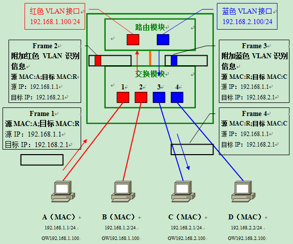
Next is the core of this talk, communication between different VLANs. Let’s consider the situation when computer A communicates with computer C.
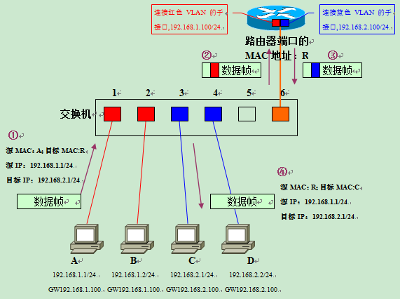
- Computer A derives from the IP address of the communication target (192.168.2.1) that C does not belong to the same network segment as this machine. So it will forward data frames to the set DefaultGateway (GW). Before sending the data frame, you need to use ARP to get the MAC address of the router.
- After getting the router’s MAC address R, the next step is to send a data frame to C as shown in the figure. In the data frame of ①, the target MAC address is the router’s address R, but the embedded target IP address is still the address of the final object C to be communicated. This part is about the communication steps when forwarding through the router in the LAN, so I will explain it in detail when I have a chance.
- After the switch receives the data frame of ① on port 1, it retrieves the table entries in the MAC address list that belong to the same VLAN as port 1. Since the aggregation link is treated as belonging to all VLANs, port 6 of the switch also belongs to the referenced object at this point. This way the switch knows that sending data frames to MAC address R needs to be forwarded through port 6.
- When a data frame is sent from port 6, it is appended with VLAN identification information because it is an aggregated link. Since it is originally a data frame from the red VLAN, it will be entered into the aggregation link with the red VLAN identification information added as shown in ② in the figure. After the router receives the data frame of ②, it confirms its VLAN identification information, and since it is a data frame belonging to the red VLAN, it is handed over to the sub-interface responsible for the red VLAN to receive it.
- Then, based on the router’s internal routing table, determine where to relay to.
- Since the target network 192.168.2.0/24 is a blue VLAN, and the network is directly connected to the router via a subinterface, it is sufficient to forward from the subinterface responsible for the blue VLAN. At this point, the destination MAC address of the data frame is rewritten to the destination address of computer C; and because it needs to be forwarded over the aggregation link, it is appended with the identifying information that it belongs to the blue VLAN. This is the data frame in figure ③.
- After receiving data frame ③, the switch retrieves the table entry belonging to the blue VLAN from the MAC address list based on the VLAN identification information. Since the communication target, computer C, is connected to port 3 and port 3 is a normal access link, the switch forwards the data frame with the VLAN identification information removed (data frame ④) to port 3, and finally computer C can successfully receive this data frame.
When communicating between VLANs, even if both communicating parties are connected to the same switch, they must go through a process of “sender-switch-router-switch-receiver”.
Layer 3 Switches
Problems when using routers for inter-VLAN routing
Now, we know that computers belonging to different VLANs can communicate with each other as long as inter-VLAN routing can be provided. However, if routers are used for inter-VLAN routing, it is likely that the routers will become a bottleneck for the entire network as traffic between VLANs continues to increase.
Switches use a dedicated hardware chip called an ASIC (ApplicationSpecified Integrated Circuit) to handle the switching of data frames, and on many models switching at cable speed (Wired Speed) is possible. Routers, on the other hand, are essentially software-based. Even if packets are received at cable speed, they cannot be forwarded out without a speed limit and therefore become a speed bottleneck. In the case of inter-VLAN routing, traffic is concentrated to the aggregated link portion of the router and switch interconnect, which is particularly prone to becoming a speed bottleneck. And from a hardware point of view, because of the need to set up separate routers and switches, in some small space environment may even become a problem to set up the place.
Layer 3 Switch
The Layer 3 Switch was created to solve the above problem. A Layer 3 switch is essentially a “Layer 2 switch with routing”. Routing is a function of the Layer 3 network layer in the OSI reference model, so a switch with Layer 3 routing is called a “Layer 3 Switch”.
The internal structure of a Layer 3 switch can be seen in the following sketch.
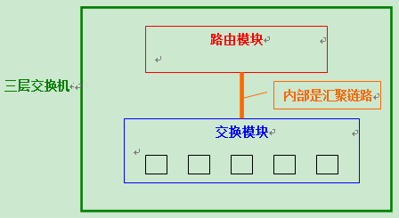
Within one local unit, a switch module and a router module are set up separately; and the built-in routing module is the same as the switch module and uses ASIC hardware to handle routing. As a result, high-speed routing is possible compared to conventional routers. Moreover, the routing and switching modules are convergently linked, and since they are internally connected, a considerable amount of bandwidth can be ensured.
Inter-VLAN routing (intra-VLAN communication) using a Layer 3 switch
How exactly does data propagate within a Layer 3 switch? Basically, it is the same as when using an aggregation link to connect a router to a switch.
Suppose there are four computers interconnected to a Layer 3 switch as shown in the figure below. When a router is used to connect, a sub-interface corresponding to each VLAN is usually set up on the LAN interface, while a Layer 3 switch generates a “VLAN Interface” (VLAN Interface) internally. VLAN Interface is the interface used to send and receive data for each VLAN. (Note: On Cisco’s Catalyst series switches, the VLAN Interface is called SVI – Switched Virtual
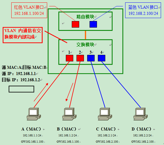
To compare with using a router for inter-VLAN routing, let’s similarly consider the situation when computer A communicates with computer B. First, a data frame with destination address B is sent to the switch; by retrieving the MAC address list of the same VLAN, it is found that computer B is connected to port 2 of the switch; therefore, the data frame is forwarded to port 2.
Inter-VLAN routing using a Layer 3 switch (inter-VLAN communication)
Next, imagine the situation when computer A and computer C communicate with each other.
- In response to the destination IP address, computer A can determine that the communication does not belong to the same network and therefore sends data to the default gateway (Frame 1).
- After retrieving the MAC address list, the switch forwards the data frame to the routing module via the internal aggregation link. When passing through the internal aggregation link, the data frame is appended with VLAN identification information belonging to the red VLAN (Frame 2).
- When the routing module receives the data frame, it first distinguishes that it belongs to the red VLAN by the VLAN identification information attached to the data frame, and accordingly determines that the red VLAN interface is responsible for receiving and routing the data. Because the target network 192.168.2.0/24 is directly connected to the router’s network and corresponds to the blue VLAN; therefore, it is then forwarded back to the switching module from the blue VLAN interface via the internal aggregation link. As it passes through the aggregation link, this time the frame is appended with the identification information of the blue VLAN (Frame 3).
- Upon receiving this frame, the switch retrieves the MAC address list for the blue VLAN and confirms that it needs to be forwarded to port 3. Since port 3 is the usual access link, the VLAN identification information is removed (Frame 4) before forwarding. Eventually, computer C successfully receives the data frame forwarded by the switch.
The overall flow is very similar to that of an external router - it goes through “sender → switch module → routing module → switch module → receiver”.
The meaning of the existence of traditional type of router
The need for routers
The price of Layer 3 switches, which were very expensive at the time of their introduction, has come down considerably. Some inexpensive foreign models are now selling for just over $10,000 when converted to RMB, and they continue to drop. Since Layer 3 switches can provide higher-speed routing than traditional routers, is there a need for routers in the network?
The answer is: “Yes”.
The necessity of using a router, mainly in the following ways.
- For connection to the WAN
- Layer 3 switches are “switches” after all. That is, most models are equipped with only LAN (Ethernet) interfaces. A few high-end switches have serial or ATM interfaces to connect to the WAN, but in most cases, the router is needed to connect to the WAN.
- Network Security
- On a Layer 3 switch, a certain level of network security can be ensured by packet filtering. However, with the various network security features provided by the router, users can build a more secure and reliable network.
- In addition to the most basic packet filtering functions, the router provides network security features such as the ability to build a VPN (VirtualPrivate Network) based on IPSec, user authentication using RADIUS, and more.
- Support for heterogeneous network architectures other than TCP/IP
- Although TCP/IP has become the mainstream of the current network protocol architecture, there are still many networks utilizing network protocols such as IPX/SPX under Novell Netware or AppleTalk under Macintosh. Layer 3 switches, except for some high-end models still basically only support TCP/IP, so the router is still essential in environments that require the use of network protocols other than TCP/IP.
Note: On a few high-end switches, the above router features can also be supported. For example, Cisco’s Catalyst 6500 series, there is an optional interface module for connecting to the WAN; there is also an optional IPSec-based module for VPN implementation; and it can also support other network protocols other than TCP/IP.
Example of a router and switch paired together to build a LAN
Let’s look at an example of a router and switch paired together to build a LAN.
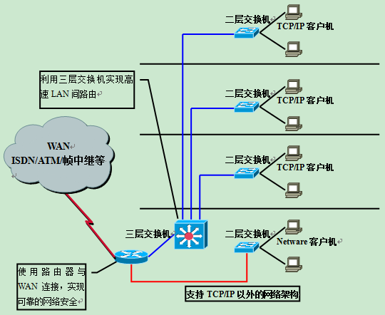
VLANs are defined using the Layer 2 switches configured on each floor to connect TCP/IP client computers. Inter-VLAN communication between floors is realized by using high-speed routing of Layer 3 switches. If the network environment requires high reliability, redundant configuration of Layer 3 switches can also be considered.
The connection to the WAN is made through routers with various network interfaces. And, network security is achieved through the router’s packet filtering and VPN functions. In addition, the use of routers can support networks beyond TCP/IP such as Novell Netware.
Only on the basis of fully mastering Layer 2 and Layer 3 switches as well as conventional routers can we compete for things and construct a highly efficient and cost-effective network.
Designing a LAN with VLANs
Features of designing a LAN using VLANs
By constructing a LAN using VLANs, users are able to freely partition broadcast domains without being restricted by physical links.
In addition, inter-VLAN routing provided by the previously mentioned routers and Layer 3 switches enables adaptation to flexible and changeable network composition.
However, since the use of VLANs tends to complicate the network composition, it can also make the composition of the entire network difficult to grasp.
It can be said that the use of VLANs has the advantage of “flexible network composition” and the disadvantage of “complex network composition”.
Let’s take a look at a specific example.
Change of network composition in a LAN without VLANs
Suppose there is a “no VLAN construction” network consisting of one router and two switches as shown in the figure.
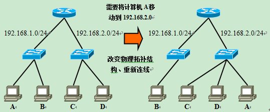
The router in the picture with 2 LAN ports. The network on the left side is 192.168.1.0/24 and on the right side is 192.168.2.0/24.
Now if you want to transfer the 192.168.1.0/24 computer A on this network to 192.168.2.0/24, you need to change the physical connection, A to the switch on the right.
And, when the need for a new address 192.168.3.0/24 network, but also in the router to occupy another LAN interface and add a switch. And because this router with only two LAN interfaces, in order to add a new network must also be upgraded to a router with more than three LAN interfaces.
Change of network composition in a VLAN-using LAN
Next, suppose there is a “VLAN-using” LAN consisting of one router and two switches. The switch and the switch and the switch and the router are aggregation links; and suppose 192.168.1.0/24 corresponds to the red VLAN and 192.168.2.0/24 corresponds to the blue VLAN.
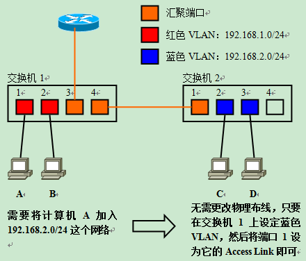
When you need to transfer Computer A connected to the network segment 192.168.1.0/24 on Switch 1 to 192.168.2.0/24, there is no need to change the physical cabling. Just generate the blue VLAN on the switch, and then add port 1 connected to computer A to the blue VLAN to make it an access link.
Then, just set the IP address, default gateway, and other information of Computer A as needed. If the IP address-related settings are obtained by DHCP, then it is possible to move between different network segments without any setting changes on the client side.
With the use of VLANs, we can freely carry out the logical design of the network without changing any physical wiring. If you are working in an environment that requires frequent changes to the network layout, the advantages of using VLANs are obvious.
And, when it is necessary to add a new segment with the address 192.168.3.0/24, it is only necessary to create a new VLAN corresponding to 192.168.3.0/24 on the switch and add the required ports to its access link.
If the network environment also requires the use of an external router, the entire operation can be completed by simply adding a new sub-interface setting on the aggregation port of the router without consuming more physical interfaces (LAN interfaces). To use a routing module that is internal to a Layer 3 switch, only one new VLAN interface is required.
The growth of a network environment is often unpredictable, and it is likely that there will often be a need to split an existing network or add a new one. These problems can be easily solved with the full live use of VLANs.
Complication of network structure by using VLANs
Although the use of VLANs allows for flexible network construction, it also brings the problem of network structure complexity.
In particular, it is difficult to accurately locate and troubleshoot faults when they occur because of the interlocking data flows.
To understand the complexity of data flow, suppose there is a network as shown in the figure below. When computer A sends data to computer C, the overall direction of the data flow is as follows.
Computer A → Switch 1 → Router → Switch 1 → Switch 2 → Computer C
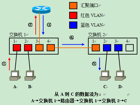
First Computer A sends data to Switch 1 (①), after which the data is forwarded to the router (②) for inter-VLAN routing. After routing, the data is then returned to switch 1 (③) from the aggregation link. Since the communication target computer C is not directly connected to switch 1, it also needs to be forwarded to switch 2 (④) via the aggregation link. At switch 2, the data is finally forwarded to port 2, where C is connected, which completes the entire process (⑤).
In this example, the data flow is already so complex with only two switches forming the network, and if VLANs are constructed across multiple switches, it is clear that the flow of each data stream will be even more difficult to grasp.
Logical and physical structure of the network
To cope with the increasing complexity of data flow, administrators need to grasp the current state of the network from both the “logical structure” and “physical structure”.
- Physical structure refers to the current state of the network as observed from the physical and data link layers, indicating the physical wiring pattern and VLAN settings of the network, etc.
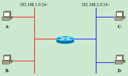
- Logical structure, on the other hand, indicates the structure of the network as observed from the network layer and above. Let’s try to analyze the logical structure of an IP network with a router in mind.
As in the previous example, the “physical structure” depicting cabling patterns and VLAN settings is shown below.
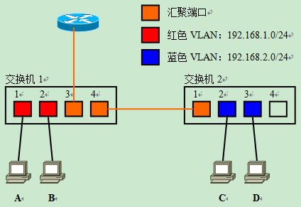
After analyzing this physical structure and converting it into a logical structure centered on the router, we get the following logical structure diagram. When we need to set up routing or packet filtering, we have to do it on the basis of the logical structure.
It is important to understand the difference between these two network architecture diagrams, especially in modern enterprise networks where VLANs and Layer 3 switches are prevalent.
Reference https://houmin.cc/posts/190a27b7/