MySQL is a widely used relational database, and understanding the internal mechanism and architecture of MySQL can help us better solve the problems we encounter in the process of using it. Therefore, I have read some books and materials related to MySQL InnoDB storage engine, and summarize them in this article.
MySQL Architecture
Two terms that are easily confused in the database world are database and instance. As common database terms, these two terms are defined in the book MySQL Technical Insider: InnoDB Storage Engine as follows.
- database: a collection of physical operating system files or other forms of file types; in a MySQL database, database files can be csv, ibd type storage files.
- Instance: MySQL database consists of background threads as well as a shared memory area.
Conceptually, a database is a collection of files, a collection of data organized according to some data model and stored in secondary storage; a database instance is a program, a layer of data management software located between the user and the operating system, and the user’s data on the database is carried out under the database instance. In MySQL, instances and databases usually correspond to each other, but in a cluster situation, there may be a database that can be used by multiple instances.
MySQL is designed as a single-process, multi-threaded architecture database and relies on the threaded implementations of various operating systems, but MySQL basically ensures consistency in physical architecture across platforms. MySQL’s architecture is shown in the following diagram.
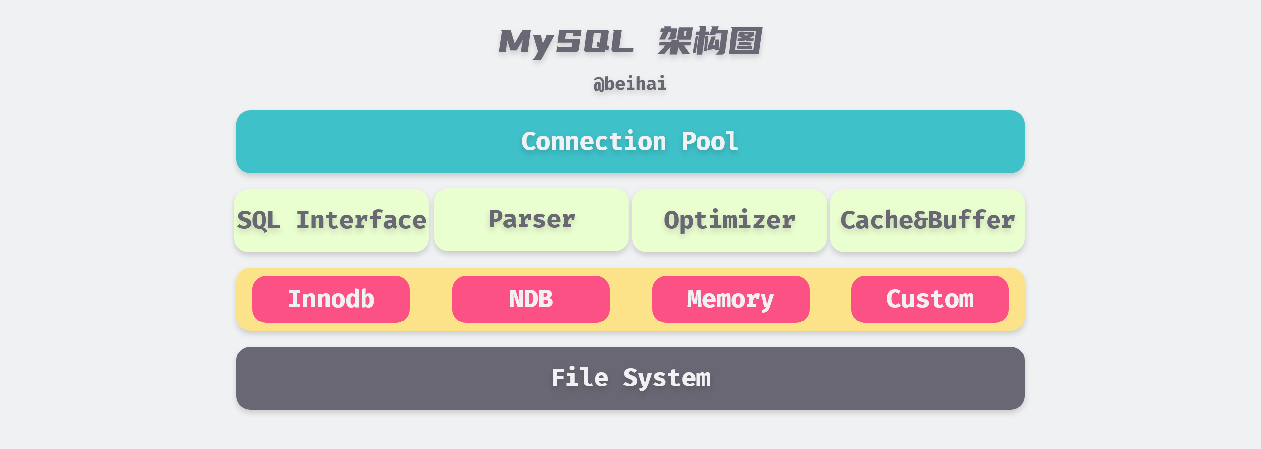
The top tier connection pool provides the services required by network clients: connection processing, authentication, security checks, etc. MySQL creates a separate thread for each client connection, and queries belonging to that connection are completed in the specified thread. The second tier contains most of MySQL’s core functionality, including parsing, analysis, optimization, caching, and built-in function handling of SQL, in addition to any functionality provided across storage engines, such as stored procedures, triggers, and views.
The third layer is the Plug-in Storage Engine, which is the most important part of MySQL. The storage engine is responsible for storing and extracting data from MySQL, and the server communicates with the storage engine through an API and writes data to disk in a format unique to each storage engine. The MySQL storage engine is table-based, and within a database instance, we can choose different storage engines for different tables depending on the characteristics of the specific application.
InnoDB is currently the most general storage engine with a good balance between high reliability and high performance, featuring support for ACID transaction model, foreign key support, row lock design, and since MySQL version 5.5.8, InnoDB has been the default storage engine and is the main target of this article.
File storage
Tablespace
In the InnoDB storage engine, each table has a Primary Key. From the logical storage structure of the InnoDB storage engine, all data is logically stored in a space, called Tablespace, according to the primary key order. From the outside, a table is composed of consecutive fixed-size Pages, but in fact, the tablespace file is organized into a more complex logical structure inside, which can be divided into Segment, Extent and Page from top to bottom.
The file logical storage structure of InnoDB storage engine is roughly shown in the following figure.
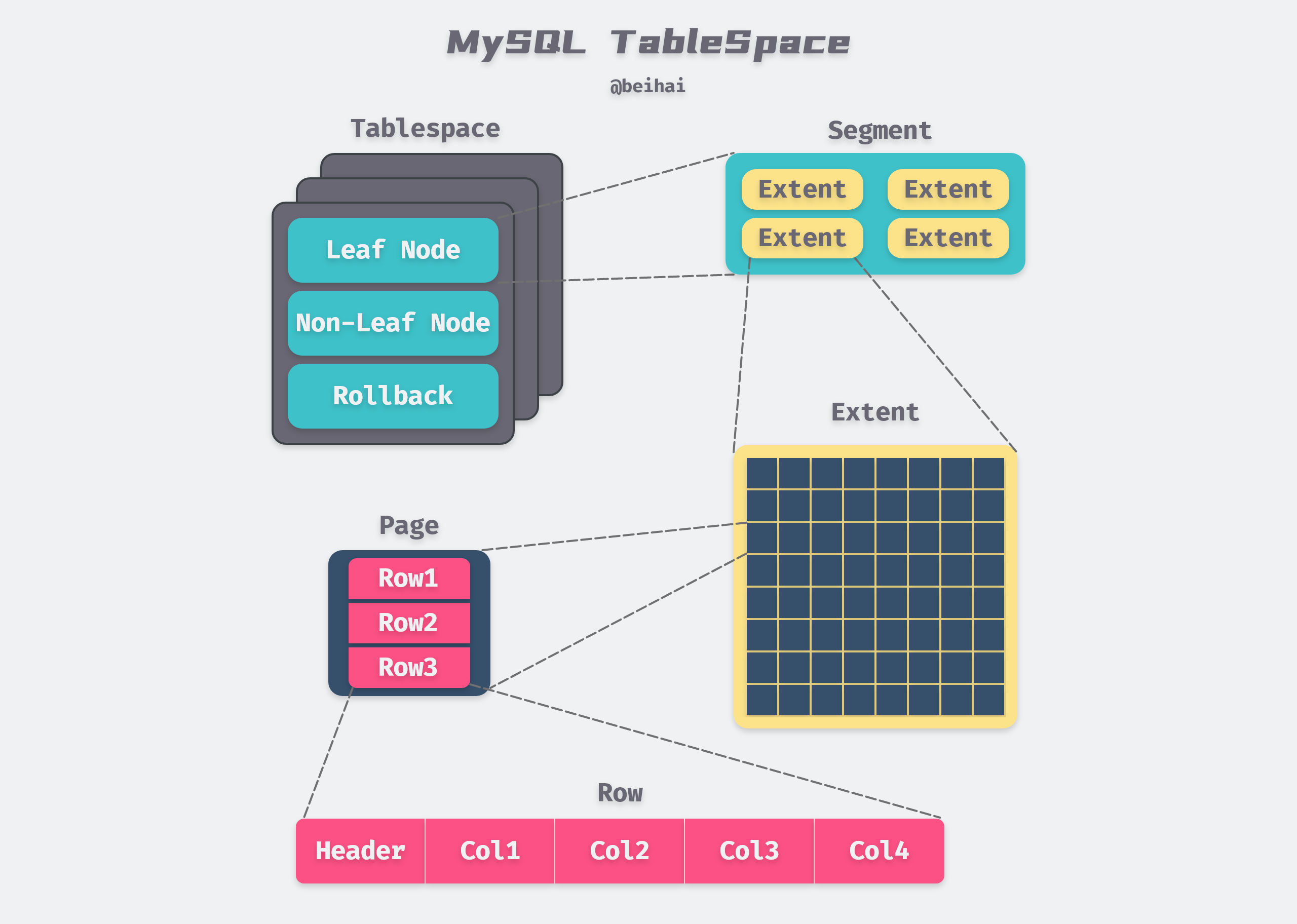
The above figure is modified from MySQL Technical Insider: InnoDB Storage Engine Figure 4-1 InnoDB Logical Storage Structure
Segment is mapped to an index in the database; within the InnoDB engine, a data segment is a leaf node of the B+ Tree and an index segment is a non-leaf node of the B+ Tree; a critical step in index creation is the assignment of Segment.
The next level of Segment is Extent, which represents a set of consecutive Pages with a default size of 1MB. Extent is used to improve the efficiency of Page allocation and better data continuity, and Segment is also allocated in Extent when it is expanded.
Page (called block in some materials) is the basic unit of tablespace data storage, InnoDB slices the table file by Page, depending on the type, Page content also differs, the most common is the data page storing row records.
By default, the InnoDB storage engine Page size is 16KB, which means there are 64 consecutive Pages in an Extent, and the Page size can be changed by specifying the innodb_page_size option when creating a MySQL instance. Note that the Page size may affect the size of Extent.
| page size | page nums | extent size |
|---|---|---|
| 4KB | 256 | 1MB |
| 8KB | 128 | 1MB |
| 16KB | 64 | 1MB |
| 32KB | 64 | 2MB |
| 64KB | 64 | 4MB |
As you can see from the table above, an Extent has a minimum of 1 MB and a minimum of 64 pages.
Data Page Structure
Page is the smallest disk unit for InnoDB storage engine to manage data, common page types are: Data (Index) Page, Undo Page, Inode Page, System Page, BloB Page, etc., where Data Page (B+Tree Node) holds the actual data of row records in the table, Data Page includes seven parts, File Header, Page Header, Max Min Record, User Record, Free space, data directory, and the end of the file. In short, the data page is divided into two parts, one part stores the data row records, which are connected by pointers according to the size of the rows, and the other part stores the data page directory, which is used to speed up the search.
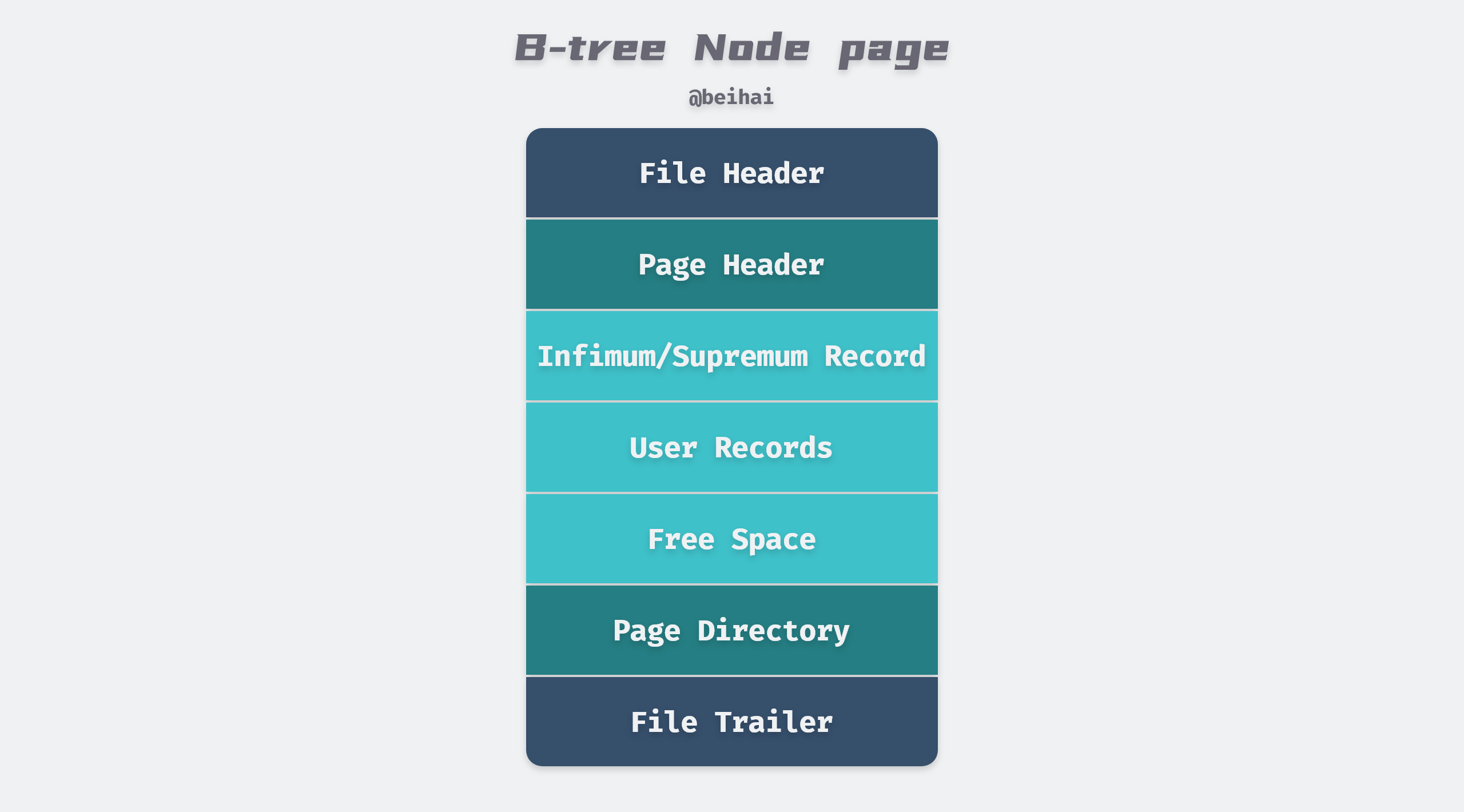
The file header and tail are mainly used to store tablespace-related information, including page numbers, page types, checksum values, etc. The file header also holds meta information related to the data page. The data directory maintains a sparse directory of the page, storing the on-page offset of a record every 4 to 8 rows. Because of the data page directory, finding and locating is relatively simple, first using a dichotomous lookup to locate the location of the two surrounding rows of data, and then using a linear lookup to locate the final location of the record.
The Infimum/Supremum Record are two dummy row records that are used to delimit the boundaries of the record. The Infimum Record is a value smaller than any primary key value in the page, and the Supremum Record is a value larger than any possible larger value. These two values are created when the page is created and will not be deleted under any circumstances.
The row record is the part of the page that is actually used to store the row record, which is a linked list data structure. To ensure the efficiency of insertion and deletion, the entire page does not sort all records in primary key order , and when the user needs to insert a record, he first looks in the space of the deleted record, and if no suitable space is found, it is allocated from Free Space. So row records may not be physically stored in primary key order; the order among them is controlled by the pointer next_record to the next record.
Row Record Format
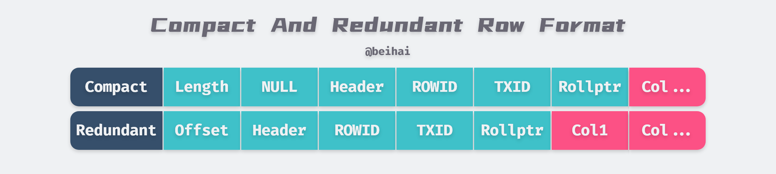
The InnoDB storage engine, like most databases, stores records as rows, each 16KB page can hold 2 to 200 row records.InnoDB’s early file format is Antelope, two row record formats can be defined, Compact and Redundant, InnoDB 1.0.x version introduced a new file format Barracuda. The Barracuda file format has two new row record formats: Compressed and Dynamic.
The Compact row record format was introduced in MySQL 5.0 and is headed by a non-NULL variable-length column length list and is placed in reverse order with the following lengths.
- 1 byte if the length of the column is less than or equal to 255 bytes.
- If the length of the column is greater than 255 bytes, it is represented by 2 bytes.
The maximum length of a variable-length field cannot exceed 2 bytes, because the maximum length of VARCHAR type in MySQL database is limited to 65535.
The second part after the variable-length field is the NULL flag bit, which indicates whether a column in the row is a NULL value, or a 1 if it is, and the NULL flag bit is also indefinite in length. Next is the record header information, which is fixed at 5 bytes.
Redundant is the row record format of InnoDB before MySQL 5.0. The head of the Redundant row record format is a list of length offsets for each column, which is also stored in reverse order. Overall, the Compact format reduces storage space by about 20%, but at the cost of increased CPU usage for some operations.
Dynamic and Compressed are variants of the Compact row record format. Compressed compresses the row data stored in it with the zlib algorithm, so it can store data of large lengths such as BLOB, TEXT, VARCHAR very efficiently.
For more details on InnoDB row formats, please refer to the documentation: InnoDB Row Formats
Row Overflow
When InnoDB stores extremely long TEXT or BLOB type of large objects, MySQL does not store everything directly in the data page. Because the InnoDB storage engine uses B+Tree to organize indexes, there should be at least two row records in each page, so if the page can only hold the next row, then the InnoDB storage engine will automatically store the row data in the overflow page.
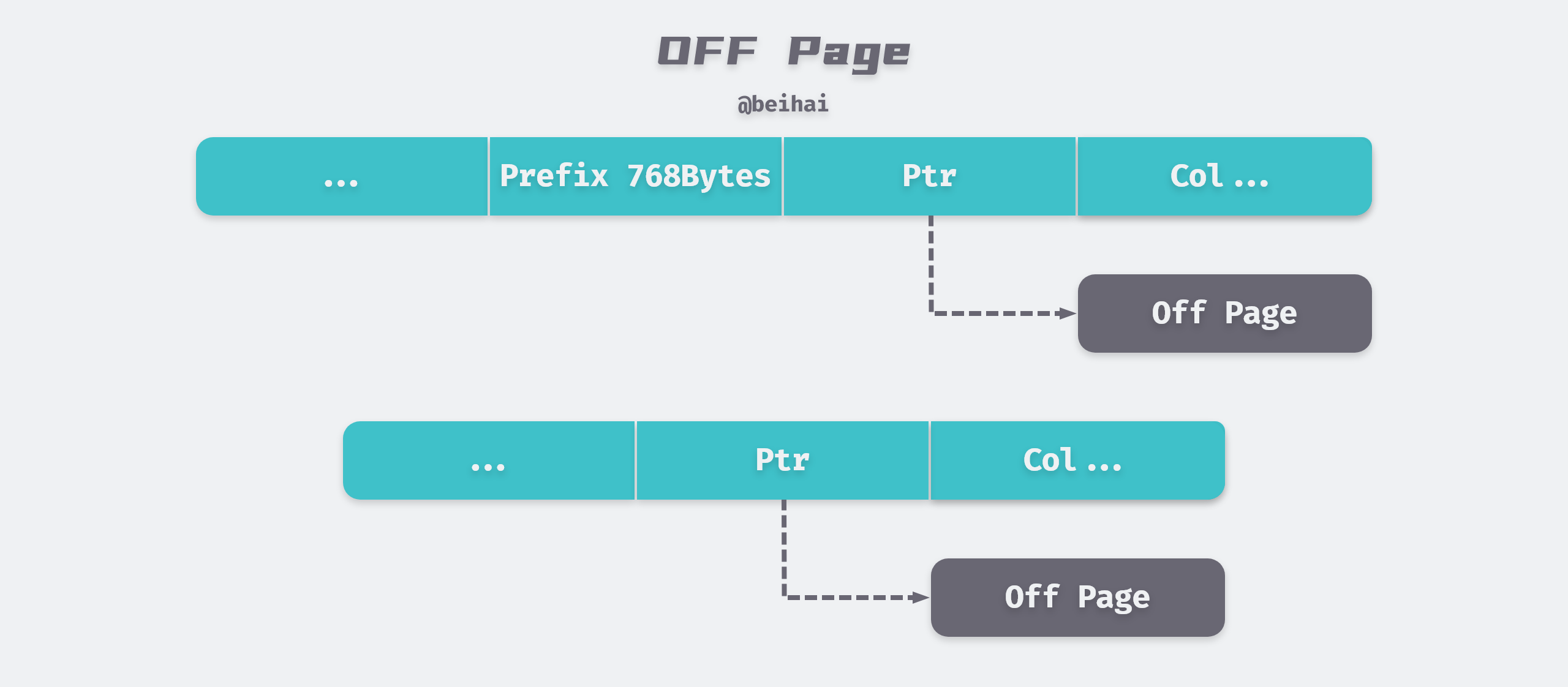
If we use Compact or Redundant format, then the first 768 bytes of row data will be stored in the data page, and the later data will be pointed to the Uncompressed BLOB Page via a pointer.
But if we use the new row record format Compressed or Dynamic only 20 bytes of pointer will be stored in the row record and the actual data will be stored in the overflow page.
Indexing
Indexing is an important aspect of application design and development. If there are too many indexes, the performance of the application may suffer. And too few indexes can have an impact on query performance. Finding the right balance is critical to application performance. the InnoDB storage engine supports the following common indexes.
- B+Tree indexes
- Full-text indexes
- Hash indexes
B+Tree Index
B+Tree is currently the most common and effective data structure for searching relational database systems. Its construction is similar to that of a binary tree, allowing data to be found quickly based on key-value pairs.
One of the characteristics of B+Tree indexes in databases is high fanout. In databases, the height of B+Tree is usually 2 to 4 levels, which means that only 2 to 4 random IOs are needed at most to find the row records of a key value.
In the InnoDB storage engine, the B+Tree index does not find a specific row for a given key; all the B+Tree index can find is the page where the row is found, and then the database reads the page into memory and then does a lookup in memory to get the data to be found.
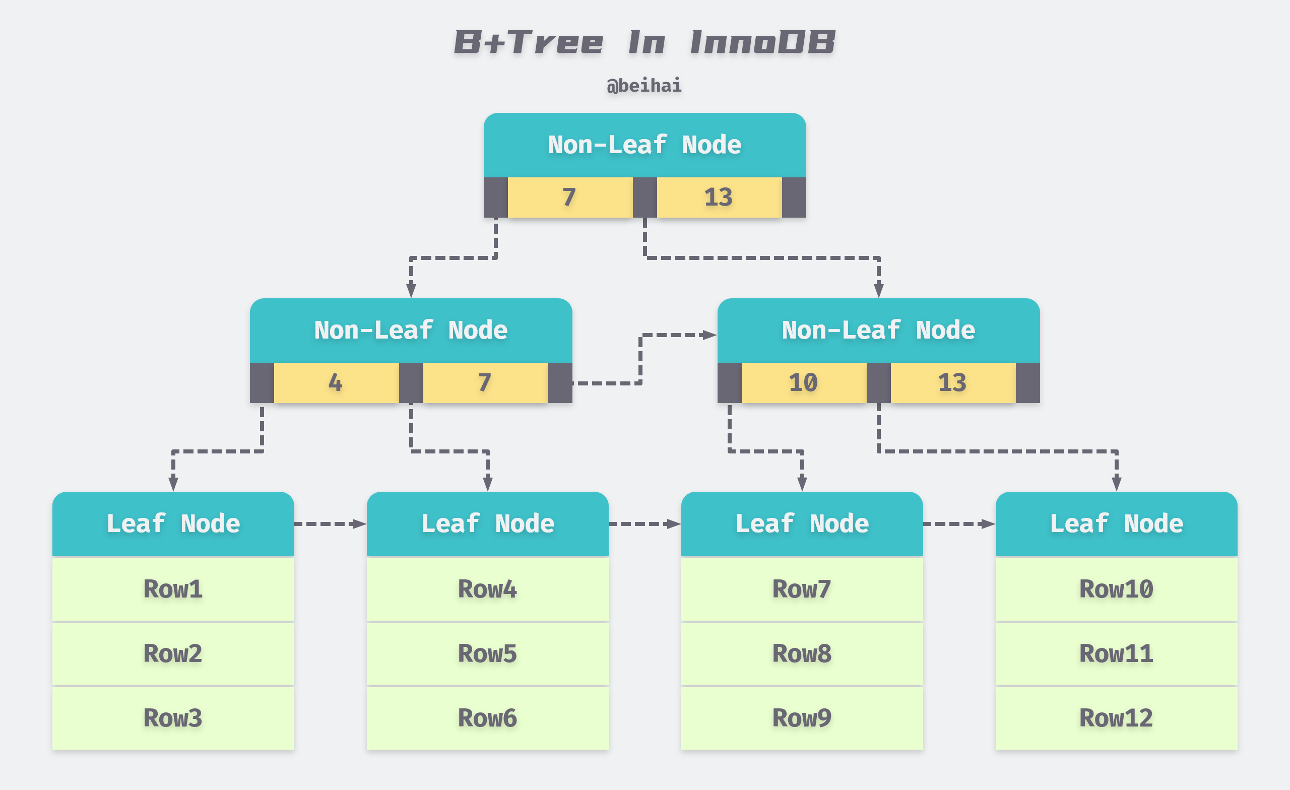
B+Tree indexes in databases can be divided into aggregated and auxiliary indexes, but whether they are aggregated or auxiliary, they are all internally B+Tree, i.e., highly balanced, with the leaf nodes holding all the data. The difference between an aggregated index and an auxiliary index is whether the leaf nodes store complete information about the rows.
Aggregate Indexes
An aggregated index is a B+Tree constructed according to the primary key of each table, while the leaf nodes store the row record data of the entire table. This feature of the aggregated index determines that the data in the index organization table is also part of the index, and like the B+Tree data structure, each data page is linked by a Doubly linked list. We can use the following SQL statement to create a test table, specify the id field as the primary key, and create an aggregated index.
Since the actual data pages can only be sorted by one B+Tree, each table can only have one aggregated index, and all row record data in the table is stored in the order of the aggregated index . In most cases, query optimizers tend to use aggregated indexes to quickly discover that a range of data pages need to be scanned because aggregated indexes can find data directly on the leaf nodes of a B+Tree index. In addition, aggregated indexes enable particularly fast access to queries against range values because of the logical order in which the data is defined.
Auxiliary indexes
The leaf node in the auxiliary index does not contain the data of the row record, but records the aggregated index (i.e. primary key) corresponding to the row data. When finding data by auxiliary index, InnoDB storage engine will traverse the auxiliary index to get the primary key of the row data, and finally use the primary key to get the corresponding row record in the aggregated index.
The existence of secondary index does not affect the organization of data in the aggregated index, so there can be more than one secondary index on each table. In the test table above, index idx_name and idx_a_b are both secondary indexes.
Federated Indexes
A federated Index is a special kind of auxiliary index. The cases discussed earlier all index only one column on a table. In the above test table, index idx_a_b is a joint index, which is also a B+ Tree in nature, but the difference is that the number of keys in the joint index is greater than or equal to 2.

As shown above, the keys of the federated indexes are stored in sorted order, and all data can be read out in logical order through the leaf nodes. Using additional columns in the index, you can narrow down the search, so the order of the columns should be carefully considered when creating a composite index.
A federated index follows the leftmost match principle, which means that the fields in the index are used from left to right. A query can use only a part of the index, but only the leftmost part. For example, if the index is key abc_index (a,b,c), then the index abc_index can be used by executing the following SQL statements.
In the third statement, although the order of a and b is reversed, the query optimizer will determine in what order this SQL statement is most efficient, so the query ends up in the same way as the second statement.
Full-text search
Full-text search is a technique to find out information about any content in an entire book or article stored in a database. It can obtain information about chapters, sections, paragraphs, sentences, words, etc. in the full text as needed, and can also perform various statistics and analysis. For example, in the following SQL statement, we can look up the articles whose blog content contains the word MySQL.
|
|
According to the characteristics of B+Tree index, even if the above SQL statement adds a B+Tree index to the content field, it still needs to scan the index to get the result, and it wastes a lot of space to create the index, and in general B+Tree index is not good for this kind of work.
Full-text search is usually implemented using inverted indexes. A backward index stores a mapping between a word and its own location in one or more documents in an auxiliary table; in layman’s terms, a backward index is used to record which documents contain a word. This is usually achieved using associative arrays, which have two representations.
- Inverted File Index: this takes the form {word, ID of the document where the word is located}.
- Full Inverted Index: this takes the form {word, (the ID of the document in which the word is located, and its location in the specific document)}.
For example, there is a table like the following.
| DocumentId | Text |
|---|---|
| 1 | Hello, I am a college student |
| 2 | I am 21 years old |
| 3 | Three years ago I came to the college |
An example of the corresponding inverted index for this table is as follows.
| Number | Text | inverted file index | full inverted index |
|---|---|---|---|
| 1 | college | 1,3 | (1:6),(3:8) |
| 2 | student | 1 | (1:7) |
| 3 | years | 2,3 | (2:4),(3:2) |
| … | … | … | … |
As you can see from the table above, the full inverted index also stores information about the location of the word, e.g., the word student is indexed as (1:7), i.e., the 7th word in document 1 is student. full inverted index takes up more space than full inverted index, but it can better locate the data and expand some of the In contrast, full inverted index takes up more space, but locates data better and expands some other search features.
InnoDB has supported full-text search since version 1.2.x, and uses the full inverted index format. In the InnoDB storage engine, the (DocumentId, Position) is treated as an ilist. Since InnoDB storage engine stores Position information in the ilist field, proximity search is possible.
In order to improve the parallel performance of full-text search, InnoDB storage engine stores the word of the inverted index into 6 auxiliary tables, each table is partitioned according to the Latin encoding of the word and stored on disk. In addition to this, a full-text search index cache (FTS Index Cache) is introduced. FTS Index Cache is a red-black tree structure, which is sorted according to (word, ilist) to speed up query operations.
Adaptive Hash Indexes
Adaptive hash indexes are part of the InnoDB buffer pool, where the InnoDB storage engine monitors the lookups of secondary indexes on a table, and if a secondary index is found to be frequently accessed, a speedup can be achieved by creating a hash index. Adaptive hash indexes are mapped to a hash table by hash functions, so they are very fast for dictionary type lookups, while for other lookup types, such as range lookups, you cannot use hash indexes.
InnoDB storage engine uses hash algorithm to lookup dictionaries, its conflict mechanism uses linked list to solve, and the hash function uses the remainder method. Since the adaptive hash index is controlled by the InnoDB storage engine itself, the DBA itself cannot interfere with it, but you can disable or enable this feature by using the parameter innodb_adaptive_hash_index, which is enabled by default.
Index design is a very complex part of the database, and this section only gives a brief overview of the internal mechanism of InnoDB indexes.
Memory Buffers
The InnoDB storage engine is based on disk storage and manages the records in it on a page-by-page basis. Due to the divide between CPU speed and disk speed, disk-based database systems often use in-memory buffering techniques to improve overall database performance.
Page Cache
InnoDB will cache the read pages in memory and take the Least Recently Used (LRU) algorithm to manage the buffer pool as a list to increase the cache hit rate.
InnoDB makes some improvements to the LRU algorithm by implementing a Midpoint Insertion Policy that defaults the first 5/8 to New Sublist, which stores frequently used hot pages, and the next 3/8 to Old Sublist. The newly read page is added to the head of old Sublist by default, and if the data of old Sublist is accessed during the run, the page is moved to the head of New Sublist.

Whenever InnoDB caches a new data page, it will look for a free cache area from the Free List first, and if it doesn’t exist, then it needs to eliminate certain tail nodes from the LRU List. Whether the data page is in New Sublist or Old Sublist, if it is not accessed, then it will eventually be moved to the tail of the LRU List as a casualty.
Change Buffer
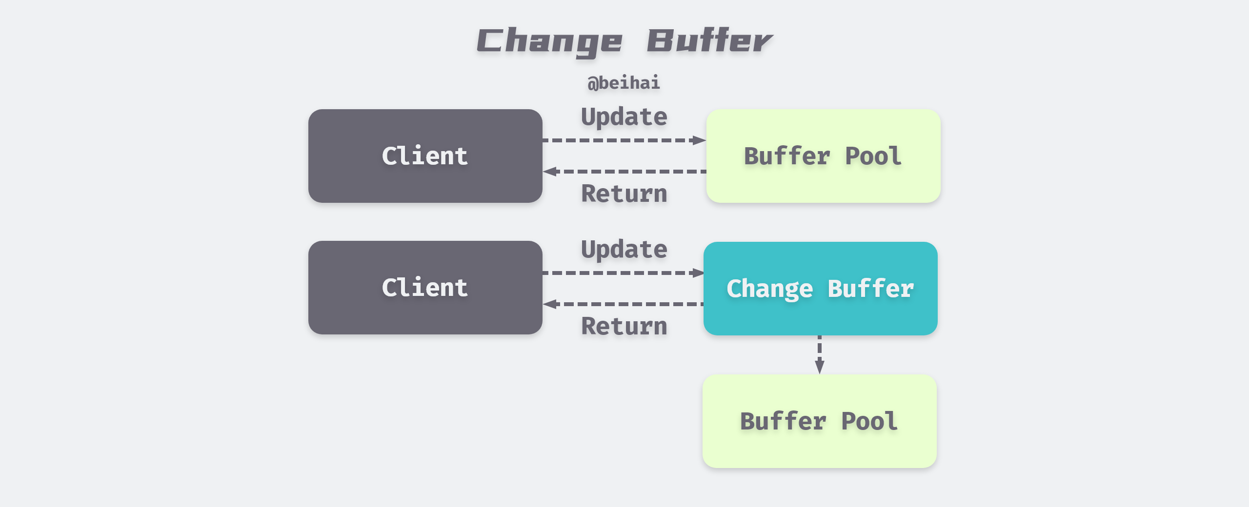
Change Buffer is used to record the modification of data, because InnoDB’s secondary indexes are different from the sequential insertion of aggregated indexes, if every modification of secondary indexes is written directly to disk, there will be a lot of frequent random IO.
InnoDB introduced Change Buffer from version 1.0.x. The main purpose is to cache the operations on non-unique secondary index pages, if the secondary index page is already in the buffer, then modify it directly; if not, then save the modification to Change Buffer first. when the corresponding secondary index page is read into the buffer, then merge the data from Change Buffer into the real one. When the corresponding auxiliary index page is read into the buffer, the data in the Change Buffer is merged into the real auxiliary index page to reduce the random IO of the auxiliary index and achieve the effect of operation merging.
Before MySQL 5.5 Change Buffer was actually called Insert Buffer, which initially only supported caching for INSERT operations, and was renamed Change Buffer as the supported operation types increased, and now the InnoDB storage engine can cache INSERT, DELETE, and UPDATE, corresponding to. Insert Buffer, Delete Buffer, Purge buffer.
Double Write Buffer
When a database goes down, it is possible that the storage engine is writing a page to a table that is only partially written, such as a 16KB page, and only the first 4KB is written before it goes down. Although data recovery can be done through logs, it is pointless to re-write the page if it is already corrupted. Therefore, InnoDB introduces Double Write Buffer to solve the half-write problem of data pages.
The default size of Double Write Buffer is 2M, which is 128 data pages. It is divided into two parts, one is reserved for batch write, which provides bulk flush of dirty pages, and the other is single page write, which is reserved for single page flush operations initiated by user threads.
When refreshing the dirty pages of the buffer pool, the dirty pages are not written directly to disk, but will be copied to the Double Write Buffer in memory first by the memcpy() function, and if the Double Write Buffer is full, then the fsync() system call will be called to write all the data of the Double Write Buffer to disk at once, as this process is sequential and the overhead is almost negligible. After ensuring that the writes are successful, the individual data pages are then written back to their own tablespace using asynchronous IO.
Locks
Locks are a key feature that distinguishes database systems from file systems, and the locking mechanism is used to manage concurrent access to shared resources. the InnoDB storage engine uses locks not only at the row level on table data, but also in multiple other places within the database, allowing concurrent access to many different resources. The implementation of locks can vary from database vendor to database vendor, and this section focuses on locks for the InnoDB engine in MySQL.
Types of Locks
InnoDB implements two types of row-level locks.
- shared locks (also called S locks): allow transactions to read a row of data. S locks can be added manually using the SQL statement
select * from tableName where ... lock in share mode;. - Exclusive lock (also known as X lock): allows a transaction to delete or update a row of data. You can use the SQL statement
select * from tableName where ... for update;to manually add an X lock.
S lock and S lock are compatible, X lock and other locks are not compatible, for example, transaction T1 obtained a row r1 S lock, transaction T2 can immediately obtain row r1 S lock, at this time T1 and T2 jointly obtain row r1 S lock, this situation is called lock compatibility, but another transaction T3 at this time, if you want to obtain row r1 X lock, you must wait for T1 to release the lock held by row r, this situation is called lock compatibility. This situation is called a lock conflict.
We can use the concept of read/write locks to understand InnoDB’s row-level locks, where shared locks represent read operations and exclusive locks represent write operations, so we can do parallel reads of row data, but only serial writes to ensure that resource competition does not occur within MySQL.
Both shared locks and exclusive locks can only lock on a certain data row. To support locking operations at different granularity, InnoDB storage engine supports an additional locking method called intent locks, which are automatically added by InnoDB and are both table-level locks.
- Intentional Shared Locks (IS): a transaction that wants to obtain a shared lock on certain rows of a table must obtain an IS lock on that table.
- Intentional Exclusive Lock (IX): a transaction that wants to obtain an exclusive lock on a table for a few rows must obtain an IX lock on that table.
Since the InnoDB storage engine supports row-level locks, intent locks do not actually block any requests other than a full table sweep; their primary purpose is to indicate whether a transaction is locking a row of data in a table. The table-level intent locks are compatible with row-level locks in the following table.
| Lock Type | X | IX | S | IS |
|---|---|---|---|---|
| X | Conflict | Conflict | Conflict | Conflict |
| IX | Conflict | Compatible | Conflict | Compatible |
| S | Conflict | Conflict | Compatible | Compatible |
| IS | Conflict | Compatible | Compatible | Compatible |
Without intent locks, when there is already a transaction using row locks to modify a row in the table, if another transaction wants to modify the whole table, it needs to scan all the rows to see if they are locked, which is very inefficient in this case; however, after the introduction of intent locks, when there is a transaction using row locks to modify a row in the table, it will first add an intent exclusion lock to the table ( IX) and then add an exclusive lock (X) to the row record. At this point, if a transaction tries to modify the whole table, it does not need to determine whether each row of data in the table is locked or not, but only needs to wait for the intentional mutex lock to be released.
– The above is from ‘A Brief Introduction’ to MySQL and InnoDB
Algorithms for row locks
Because the InnoDB storage engine supports row-level locks, this subsection looks at the algorithms for implementing row locks. The InnoDB storage engine uses three algorithms for row locks to meet the requirements of the relevant transaction isolation level.
-
Record Lock: this lock is a lock on indexed records, if no index is defined in the table, InnoDB will create a hidden aggregated index for the table by default and use the index to lock the records; if we use an aggregated index or auxiliary index field as a filter condition in the
WHEREstatement in SQL, then InnoDB will If we use an aggregated index or a secondary index field as a filter condition in theWHEREstatement in SQL, then InnoDB can find the row through the B+ Tree created by the index and add a lock, but if we use an unindexed field as a filter condition, InnoDB will lock the whole table because it doesn’t know where the row to be modified is stored, and it can’t tell which row will be modified in advance. -
Gap Lock: This lock locks a range, but not the record itself; when a range query SQL statement like
SELECT * FROM table WHERE age BETWEEN 20 AND 30 FOR UPDATE;is used, it prevents other transactions from inserting a record withage = 15into the table. Because the entire range is locked by the gap lock. Although there are shared locks and exclusive locks in gap locks, they do not conflict with each other, that is, different transactions can hold both shared locks and exclusive locks for the same range, which are used to multiple transactions adding new rows to the same range to avoid phantom read problems. -
Next-key Lock : This lock is a combination of Record Locks and Gap Locks, which locks a range and locks the record itself. For example, if an index has three values 1, 3, 5, then the index locks the range
(-∞,1], (1,3], (3,5], (5,+ ∞).Although it is called Next-Key Lock, what it locks is not the current value and the range after it, but actually the current value and the range before it.
When we update a row, such as
SELECT * FROM table WHERE index = 3 FOR UPDATE;, InnoDB not only adds Next-Key Lock to the range(1, 3], but also adds Gap Lock to the range(3, 5]after this row, so the rows in the range(1, 5]will be locked. InnoDB uses Next-key Lock and Gap Lock to solve the phantom read problem. Note that InnnoDB automatically degrades Next-key Lock to Record Lock if the index has a unique attribute.
Consistent non-locking reads
Consistent reads in InnoDB refer to querying a snapshot of the database at a point in time using MVCC (Multiple Version Concurrency Control) technology. This query can see changes made by transactions committed before that point in time and will not be affected by subsequent changes or uncommitted transactions. For example, if the row being read is performing a DELETE or UPDATE operation, the read operation will not wait for the row lock to be released; instead, the InnoDB storage engine will read a snapshot of the row’s data.
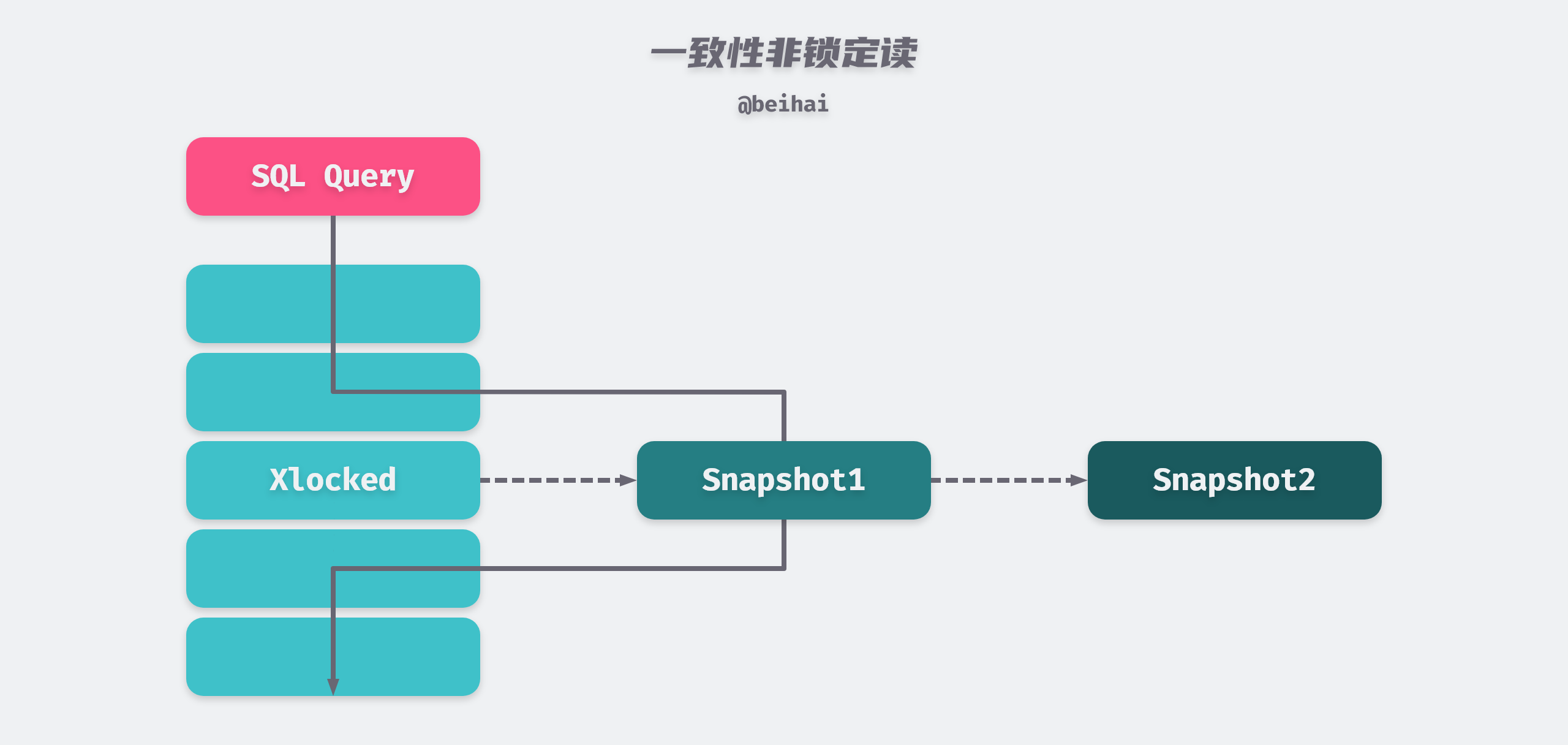
Because there is no need to wait for X locks to be released on the rows accessed, consistent non-locking reads greatly improve concurrent read performance of the database. As you can see from the above diagram, snapshot data is actually the previous historical version of the current row data, and there may be multiple versions of each row record, which is implemented by Undo Log Segments. The way of reading will be different under different transaction isolation levels.
- When the transaction isolation level is REPEATABLE READ, consistent reads in the same transaction are read from the snapshot created by the first query under that transaction.
- When the transaction isolation level is READ COMMITTED, the consistency reads under the same transaction all create and read the latest snapshot of this query itself.
Deadlock
Deadlock is a phenomenon caused by two or more transactions competing for lock resources during execution and waiting for each other, without external force, they will not be able to continue execution.InnoDB engine adopts the Wait-For-Graph method to automatically detect deadlock, and will automatically roll back a transaction if deadlock is found.
The Wait-For-Graph keeps lock information chain and transaction wait chain in the database, and the above chain can construct a graph, if there is a loop in this graph, it means there is a deadlock and transactions are waiting for each other to release resources.
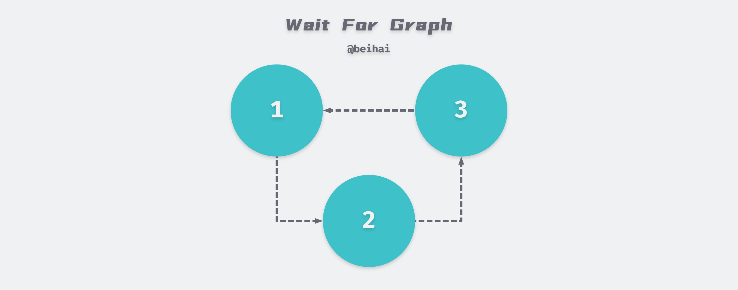
The wait graph is a more proactive deadlock detection mechanism that determines whether a loop exists when each transaction requests a lock and a wait occurs. In the above figure, transaction 1 needs transaction 2 to release resources to continue execution, while transaction 2 needs transaction 3 to release resources… eventually forming a deadlock loop, which will automatically roll back a transaction to unlock the deadlock competition, usually the InnoDB storage engine chooses to roll back the transaction with the least amount of Undo.
Transactions
A database transaction is a logical unit in the execution of a database management system, consisting of a finite sequence of database operations. Transactions have four important characteristics: Atomicity (Atomicity), Consistency (Consistency), Isolation (Isolation), Durability (Durability), people used to call ACID characteristics.
Transaction isolation is achieved by the locking mechanism described above, Redo Log is used to ensure that transactions are atomic and persistent, and Undo Log is used to ensure that transactions are consistent.
Both Redo and Undo can be thought of as recovery operations, with Redo recovering the page operations modified by the commit transaction and Undo rolling back the row log to a specific version, so there are some differences in what is logged between the two.
Redo Log and Persistence
Persistence means that once a transaction is committed, the result is permanent. Even in the event of a downtime failure, the database can recover the data, which means that after the transaction completes, all updates to the database from the transaction will be saved to the database and cannot be rolled back.
The InnoDB storage engine uses a redo log to achieve transaction persistence, which consists of two parts: a redo log buffer in memory; and a redo log file persistent on disk. The Redo Log File records the physical changes to the data pages, for example, if a transaction with transaction number T1 modifies data X, and the original value of X is 5 and the modified value is 15, then the Redo Log record is <T1,X,15> and the Undo Log record is <T1,X,5>.
InnoDB achieves transaction persistence through Force Log at Commit mechanism, that is, when the transaction COMMIT, all Redo Log and Undo Log of the transaction must be written to the redo log file for persistence first, and the transaction COMMIT operation is completed before it is considered successful. The Redo Log is essentially sequential, so there is no need to read the Redo Log file while the database is running, but in the event of server downtime, MySQL uses the Redo Log to recover the unsynchronized content. To ensure that every log is written to the redo log file, the InnoDB storage engine needs to call the fsync() system call once after each redo log cache is written to the redo log file to write the data to disk immediately.
To better understand the relationship between redo logging and data buffering, we can describe the process with the following example.
- the client opens a new data modification transaction T1, which reads data X from the disk into the memory buffer.
- modifying the data X from the original value of 5 to 15, while the data is still in the memory buffer, waiting to be flushed to disk.
- record the data modification record
<T1,X,15>in the Redo Log and immediately callfsync()to write the data to disk. - The transaction can be committed successfully only after the third step is completed, and the data in the memory buffer is flushed to disk.
Note that the Redo Log is generated right after the transaction starts, and the Redo Log disk drop is not written as the transaction is committed, but starts to be written to the Redo Log file during the execution of the transaction. Once the dirty pages of the corresponding transaction are written to disk, the Redo Log’s mission is complete and the space it occupies can be reused.
In the InnoDB storage engine, the redo log cache and redo log files are stored in blocks of 512 bytes each. If the number of redo logs generated in a page is larger than 512 bytes, then it needs to be split into multiple redo log blocks for storage. In addition, since the size of the redo log block is the same as the disk sector size, which is 512 bytes, the atomicity of the redo log writes can be guaranteed.
Undo Log and Consistency
Consistency means that a transaction changes the database from one state to another consistent state. The integrity constraints of the database are not broken before the transaction starts and after it ends. A transaction is a unit of consistency, and if an action in a transaction fails, the system can automatically undo the transaction - returning to the initialized state.
Undo is stored in a special segment Undo Segment inside the database, located in the shared tablespace. undo is logical logging and does not physically restore the database to the way it was before the statement or transaction was executed, but only logically restores the database to its original state. All changes are logically undone, but the data structures and pages themselves may be very different after the rollback. This is because in a multi-user concurrent system, there may be tens, hundreds, or even thousands of concurrent transactions, with one transaction modifying a few rows on the current page while other transactions are modifying several other rows on the same page. Therefore, it is not possible to roll back a page to the way it was at the beginning of the transaction, because this would affect the work being done by other transactions.
In addition to the rollback operation, the implementation of MVCC mentioned in the Consistent Non-Locking Reads subsection is also accomplished through Undo. When a user reads a row that is already occupied by another transaction, the current transaction can read the previous row version information through the Undo log, thus achieving a non-locking read.
Undo Log also generates Redo Log at runtime, because Undo Log also needs persistence protection.
Locks and Isolation
Isolation requires that the objects of each read and write transaction be separated from the objects of other transactions, i.e., the transaction is not visible to other transactions until it commits. It can also be understood that when multiple transactions are accessed concurrently, the transactions are isolated from each other and one transaction should not affect the operation of other transactions.
MySQL guarantees the isolation of transactions through the locking mechanism.
The four isolation levels defined by SQL standard are adopted by ANSI (American National Standards Institute) and ISO/IEC (International Standard), and each level will have different degrees of impact on the processing ability of transactions. Before we describe each of the four isolation levels from highest to lowest level of concurrency and demonstrate them in code, we create a demo table test and prepare two clients client1 and client2.
READ UNCOMMITTED - Dirty Reads
A transaction at this isolation level reads data from other uncommitted transactions, also known as dirty reads, as shown below.
|
|
The last step of client2 reads the uncommitted transaction in client1 (no commit action), i.e., a dirty read, which is the best concurrency for the database at this isolation level.
READ COMMITTED - non-repeatable reads
If a transaction can read another committed transaction, multiple reads will result in different results, a phenomenon called Non-repeatable reads.
|
|
After client2 opens a transaction, the first time it reads the test table (when client1’s transaction has not yet committed) the id is 1, and the second time it reads the test table (when client1’s transaction has already committed) the id has changed to 2, indicating that the committed transaction has already been read at this isolation level.
REPEATABLE READ - phantom read
In the same transaction, the result of SELECT is the state at the point in time when the transaction started, so the same SELECT operation will read the same result, but there will be phantom read phenomenon.
|
|
The above code proves that no other transaction has been read under this isolation level, but if you then insert a data in client2, a primary key conflict error will occur, as if the previous query was an illusion.
REPEATABLE-READ is the default isolation level supported by the InnoDB storage engine. From the above description, we can see that REPEATABLE READ and READ UNCOMMITED are actually contradictory, if the former is guaranteed, you can’t see the committed transaction, if the latter is guaranteed, it will lead to different results for the two queries. InnoDB chooses to use the next-key lock mechanism mentioned above in the REPEATABLE READ isolation level to avoid the problem of phantom reads.
SERIALIZABLE - Serialization
At this isolation level transactions are executed serially and sequentially, thus avoiding the dirty read, non-repeatable repeat and phantom read problems described above.
Once the transaction commits, client2 will immediately return the record with id 1, otherwise it will keep blocking until the request times out. the InnoDB engine of MySQL database will implicitly add a read shared lock to the read operation to achieve serialization level transaction isolation, but since every SELECT statement will be locked, the database concurrency of this isolation level is also the weakest.
The above four isolation levels are getting more and more isolated, but the corresponding concurrency performance is getting lower and lower. MySQL chooses the REPEATABLE READ isolation level and uses the next-key lock mechanism to avoid the phantom read problem, which is also a compromise solution.
Summary
The main features of MySQL are summarized in this article, but the knowledge about MySQL is very complicated, so readers who want to understand the specific details of the implementation can read the relevant books or official documentation.
Reference
- https://wingsxdu.com/posts/database/mysql/innodb/
- File Space Management
- InnoDB Row Formats
- MySQL - Engine Features - InnoDB Data Pages Explained
- MySQL - Engine Features - InnoDB Buffer Pool
- Buffer Pool
- InnoDB Locking
- Locks in MySQL
- MySQL Transaction Isolation Levels and Locks
- MySQL and InnoDB: A Brief Introduction
- Inside MySQL Technology: InnoDB Storage Engine