The bridge network model we introduced in the previous note is mainly used to solve the problem of containers accessing each other between the same host and containers exposing services to the outside world, and does not address how to solve the problem of containers accessing each other across hosts.
For the inter-host container access problem, we can think of the most intuitive solution is to use the host network directly, in this case, the container completely reuse reuse the host network equipment and protocol stack, container IP is the host IP, so that, as long as the host host can communicate, the container will naturally be able to communicate. However, in order to expose container services, each container needs to occupy a port on the host, through which the port and the outside world communication. Therefore, it is necessary to maintain the port assignment manually, and it is not possible to make different container services run on one port, because of this, this container network model is difficult to be extended to the production environment.
Therefore, the feasible solution for cross-host communication is to let the container configure a different IP address from the host, often on top of the existing layer 2 or layer 3 network and then build up a separate overlay network, which usually has its own independent IP address space, switching or routing implementation. Since the container has its own independently configured IP address, the underlying network devices such as switches and routers in the underlay plane do not sense the existence of these IPs at all, which results in the container’s IP not being directly routed out to achieve cross-host communication.
In order to solve the problem of access between container independent IP addresses, there are two main ideas.
- modify the underlying network device configuration, add the management of container network IP addresses, modify the router gateway, etc. This approach is mainly combined with SDN (Software define networking).
- No modification to the underlying network device configuration, reuse the original underlay plane network to solve the container cross-host communication, there are mainly the following two ways.
- Tunneling (overlay): Encapsulate container packets into Layer 3 or Layer 4 packets of the host network, then use the host’s IP or TCP/UDP to transmit to the target host, and then forward to the target container after the target host unpacks. overlay tunneling common solutions include VxLAN, ipip, etc. Currently, the mainstream container networks using Overlay tunneling technology include Flannel, etc.
- Modify host routing: add the container network to the routing table of the host network, the host network device as a container gateway, through the routing rules forwarded to the specified host, to achieve the three layers of container communication with each other. Current networks that implement container cross-host communication through routing techniques such as Flannel host-gw, Calico, etc.
Technical Terms
Before we start, let’s summarize some of the various technical terms we often see inside the introduction to container networking articles.
- IPAM (IP Address Management): IP address management is not a term unique to the container era, traditional standard network protocols such as DHCP is actually a kind of IPAM, responsible for distributing IP addresses from MAC addresses; but in the container era we refer to IPAM, we specifically refer to the allocation and recovery of IP addresses for each container instance, to ensure that all containers in a cluster are assigned a globally unique IP address; mainstream practices include: based on CIDR to ensure that all containers in a cluster are assigned a globally unique IP address; mainstream practices include: CIDR-based IP address segment allocation or precise IP assignment for each container.
- overlay: in the container era, a separate network plane built on top of the host’s existing layer 2 (data link layer) or layer 3 (IP network layer), this overlay network usually has its own separate IP address space, switching or routing implementation.
- IPIP: A tunneling protocol based on the TUN implementation of a Linux network device that allows Layer 3 (IP) network packets to be sent and received encapsulated on top of another Layer 3 network packet.
- IPSec: similar to the IPIP tunneling protocol, a point-to-point encrypted communication protocol that is typically used in data tunnels for overlay networks.
- VxLAN: The solution jointly proposed by VMware, Cisco, RedHat, etc. to solve the problem that the number of virtual networks supported by VLAN (4096) is too small; VxLAN can support the division of up to 16 million virtual networks in a VPC (Virtual Private Cloud).
- BGP: Routing Protocol for Backbone Autonomous Networks. The contemporary Internet consists of many small AS (Autonomous system) autonomous networks, and the Layer 3 routing between autonomous networks is implemented by the BGP protocol. In simple terms, through BGP protocol AS tells other AS which IP address segments are included in their own subnet, their AS number and some other information.
- SDN (Software-Defined Networking): a broad concept for rapid configuration of networks by software, often including a central control layer to centrally configure the underlying infrastructure network facilities.
docker native overlay
docker natively supports overlay networks to address cross-host communication between containers. In fact, Laurent Bernaille at DockerCon 2017 broke down the implementation of the overlay network natively supported by docker, and even has a step-by-step tutorial on implementing the network model from scratch, which The three articles are listed below.
- Deep dive into docker overlay networks part 1
- Deep dive into docker overlay networks part 2
- Deep dive into docker overlay networks part 3
So here I’ll just give a general overview of how the docker native overlay network model works.
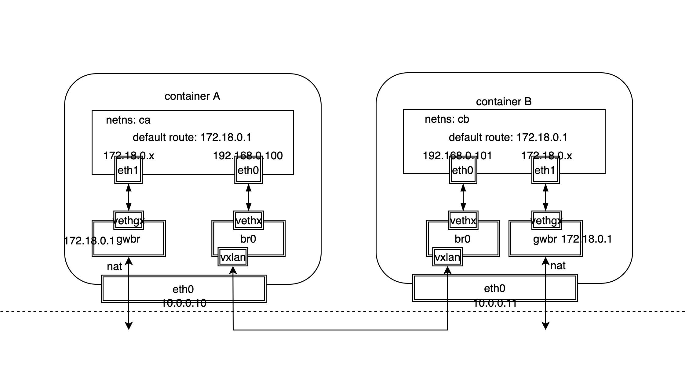
As you can see from the above network model diagram, for docker native overlay network, different Linux network devices are used to handle the north-south traffic for outbound container access and the east-west traffic for inter-container access.
- North-south traffic: similar to the bridge network model, the bridge device of the host acts as the gateway, then use the veth device pair to connect the host bridge and the container NIC device respectively, and finally send and receive the external packets through the host NIC, it should be noted that the external packets need to do address translation.
- East-West traffic: additionally add a separate bridge device on the host, and then use the veth device pair to connect the host bridge and the intra-container NIC device respectively, while the host intra-bridge device also binds the VxLAN device, the VxLAN device encapsulates the cross-host container packets into VxLAN packets sent to the target host, and then unencapsulates and forwards them to the corresponding containers.
It should be noted that although two containers across hosts are communicating through the overlay network, the containers themselves cannot sense it because they only think that they are in a subnet with each other and only need to know each other’s MAC addresses, and can learn to get IP and MAC address translation by broadcasting through ARP protocol. Of course, there is no problem in theory to broadcast ARP packets through VxLAN tunnel, the problem is that this scheme will lead to too many broadcast packets and the cost of broadcasting will be very large.
The solution given by docker is to solve the ARP broadcast problem by ARP proxy + static configuration, where the address information of containers is saved to the KV database etcd. This replaces the use of ARP broadcast by populating the IP and MAC address tables (neigh tables) with static configurations, so the VxLAN device is also responsible for the local container ARP proxy.
PERMANENT in the above neign information represents static configuration rather than acquired through learning. And 192.168.0.103 and 192.168.0.104 are the IP addresses of the other two containers. Whenever a new container is created, docker updates the local neigh information table by notifying the node.
In addition, packets between containers are eventually transmitted through VxLAN tunnels, so it is necessary to know which node is the target container of the packet. When the number of nodes reaches a certain order of magnitude, if the same broadcast flooding as ARP is used to learn, then obviously there are also performance problems, and in practice, this solution is rarely used, in the hardware SDN usually use BGP EVPN technology to achieve the control plane of VxLAN, and docker solution is similar to ARP, through the static configuration of the way to populate the VTEP ( VxLAN Tunnel Endpoint) table by static configuration, we can see the forwarding table of container network namespace (FDB: Forward DataBase).
The forwarding table information above indicates that the MAC address 82:fa:1d:48:14:04 has a VTEP address of 10.0.0.10 on the opposite end and 82:fa:1d:48:14:04 has a VTEP address of 10.0.0.10 on the opposite end, permanent indicates that both forwarding table records are statically configured, and these The source of the data is still the KV database etcd, and these VTEP addresses are the IP addresses of the hosts where the containers are located.
Flannel
Flannel is one of the most dominant container network implementation models, supporting both overlay and modified host routing modes.
Unlike docker’s native overlay network, where all nodes share a single subnet, Flannel is typically initialized with a 16-bit network and then each node is assigned a separate 24-bit subnet. Since the nodes are all on different subnets, cross-node communication is essentially a Layer 3 communication, and there is no Layer 2 ARP broadcast problem.
In addition, what makes Flannel so simple and elegant is that unlike docker’s native overlay network, which requires a bridge device inside the container dedicated to overlay network communication, Flannel uses only docker’s most native docker0 network, which requires little change to the The original docker network model is virtually unchanged, except for the need to configure subnets for each node.
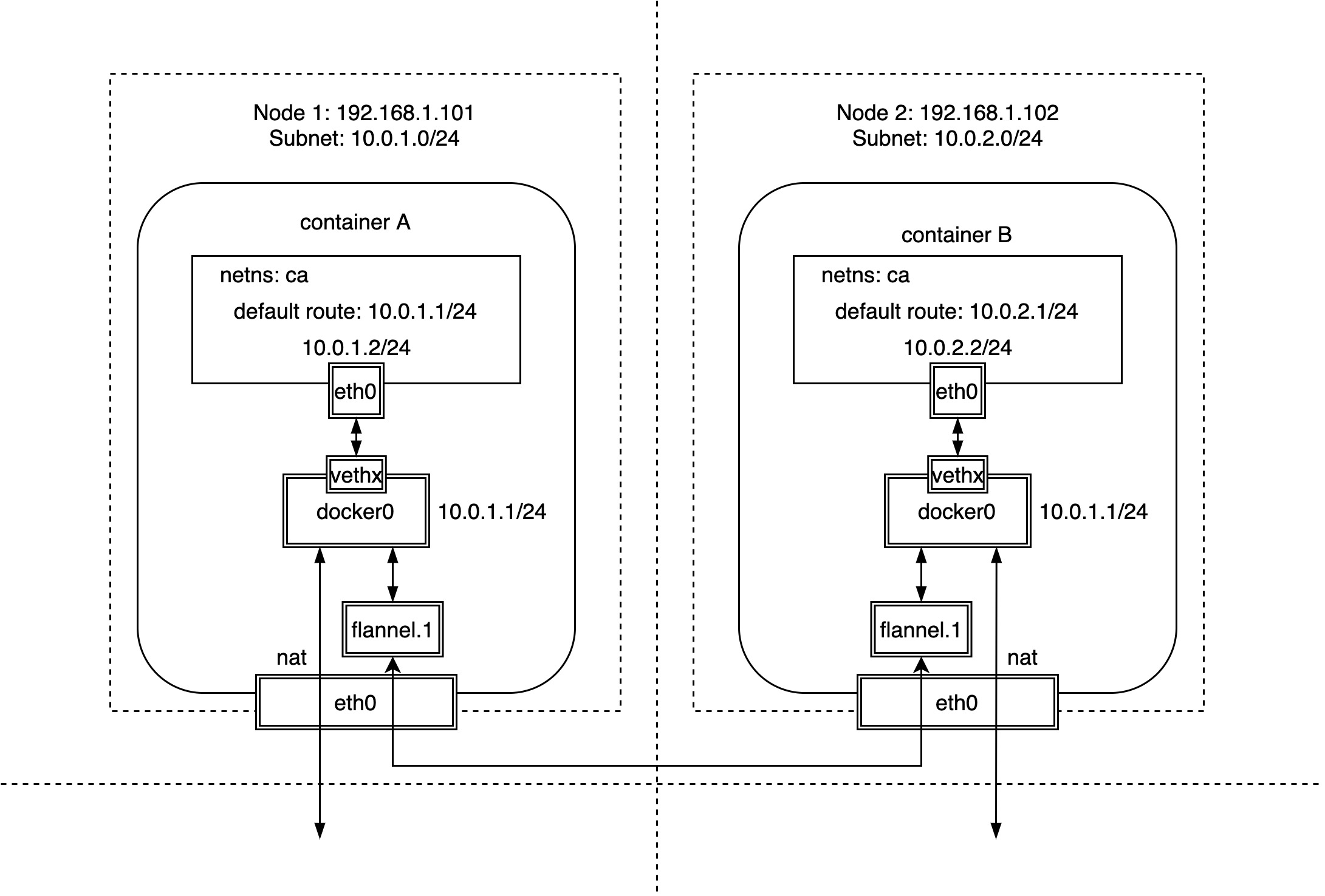
As you can see in this diagram above, Flannel assigns a separate subnet to each node based on docker’s most native docker0 bridge device and veth device pair.
| Node Name | Node IP | Node Subnet |
|---|---|---|
| Node 1 | 192.168.1.101 | 10.0.1.0/24 |
| Node 2 | 192.168.1.102 | 10.0.2.0/24 |
We can also see that access to containers for external traffic and access between containers on the same host is exactly the same as docker’s native bridge mode. So, how do we access containers across hosts?
As mentioned earlier, Flannel provides both “overlay” and “modify host routes”. The overlay method is mainly through VxLAN tunnels, while modifying host routes is done by configuring static host routes.
VxLAN tunnel
View the local static route for host node1.
As you can see, for each host, the current subnet can be accessed directly through the docker0 bridge, while the other subnets require a special network device flannel.1, which is a Linux VxLAN network device, where .1 is the VNI value and the default value is 1.
Because containers on the same host are on the same subnet, they can be obtained directly by ARP learning, while containers on different hosts are on different subnets, so there is no ARP broadcast flooding involved. However, how does the VxLAN network device flannel.1 know the VTEP address on the other side? Let’s take a look at the forwarding table FDB.
Where 192.168.1.102 is the IP address of the other node, the VTEP address, and 82:fa:1d:48:14:00 is the MAC address of the peer network device, flannel.1. As you can see from permanent, the forwarding table is added statically by Flannel, and this information can be stored in etcd.
Compared to docker’s native overlay network, the creation and deletion of containers does not require Flannel intervention at all, except for adding or deleting nodes, which requires Flannel to configure static routes and forwarding tables to the FDB, and in fact Flannel does not need to know if new containers are created or deleted.
host-gw routing
Above, we introduced Flannel’s ability to build overlay networks through VxLAN tunnels to enable cross-host communication between containers. In fact, Flannel also supports cross-host communication between containers through host-gw, i.e. by modifying the host route. In this case, each node is equivalent to a router that acts as a gateway for containers and is responsible for routing and forwarding network packets between containers.
We’ll have a chance to go into more detail about Flannel’s “host-gw modify host route” implementation later. It should be noted that the host-gw approach is better than the overlay approach because it eliminates the VxLAN packet unpacking process and routes packets directly to the destination address. However, because it is achieved by adding static routes, each host is equivalent to the gateway to the container, so each host must be in the same subnet, otherwise the cross-subnet due to “link-layer inaccessible” resulting in the failure to achieve routing.
Calico
Calico uses a similar approach to Flannel “modify host route host-gw” for cross-host communication between containers. The difference is that Flannel adds host static routes one by one through the flanneld process, while Calico broadcasts through the BGP protocol for mutual learning of routing rules between nodes.
Calico assigns a subnet to each host node just like Flannel, except that Calico assigns a 26-bit subnet by default, unlike the 24-bit subnet that Flannel assigns by default.
| Node Name | Node IP | Node Subnet |
|---|---|---|
| Node 1 | 172.16.31.155 | 10.1.83.192/26 |
| Node 2 | 172.16.32.117 | 10.1.32.192/26 |
| Node 2 | 172.16.32.120 | 10.1.147.128/26 |
Calico dynamically adjusts routes via BGP protocol, so let’s take a look at the routing rules for hosts.
As you can see, Calico modifies host routing to achieve cross-host communication between containers in the same way as Flannel host-gw, where the next hop is directed to the IP of the corresponding host, using the host as the gateway to the containers. However, Calico adds a blackhole rule to discard access packets to illegal container IPs. Another difference is that once the packet reaches the host, Flannel forwards the traffic through the route to the bridge network device, which forwards it to the container, while Calico generates a routing rule for each container IP that points directly to the container’s NIC counterpart. When the number of containers reaches a certain size, the number of host routing rules will also increase, and performance will be an issue, Calico’s solution is a route reflector.
In addition, it is important to note that we know that the Flannel host-gw approach only supports adding static routing rules if each host is on the same subnet, and cannot support hosts across network segments, so does Calico support that?
The answer is yes. Calico can be installed with or without ipip mode, which means ipip tunneling. In my experimental environment, ipip mode is turned on, and if you look closely enough, you will see that the host routes to containers on other hosts go through the tunl0 network device, so let’s take a look at the type of tunl0 network device.
As you can see, tunl0 is actually a TUN network device for Linux, it will open IPIP tunnels between different host nodes, which means that even if the host node is in a Layer 3 network, packets can still be sent to the target host through the tunnel, and then forwarded by the target host to the corresponding container, at this point Calico actually uses the overlay implementation.