In the previous notes, we briefly saw a way to implement VPN through TUN/TAP devices when introducing Linux network devices, but did not practice how TUN/TAP virtual network devices function exactly in Linux. In this note we’ll take a look at how to implement IPIP tunnels based on TUN devices in the cloud computing space.
IPIP Tunneling
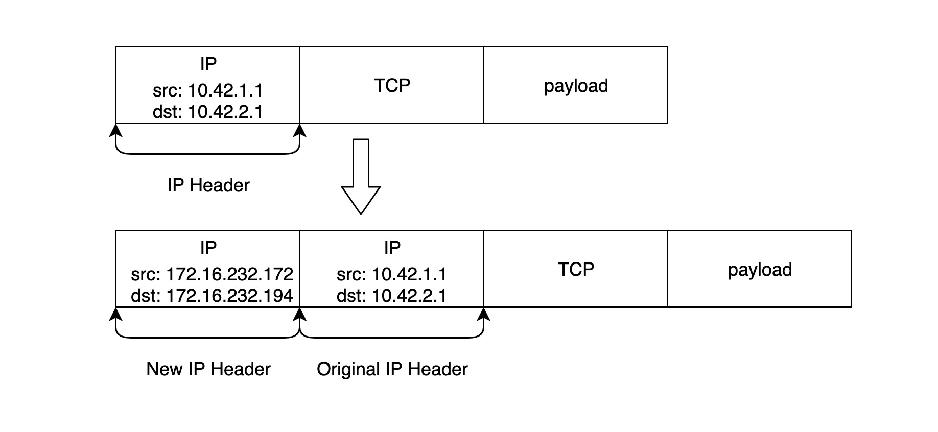
As we mentioned in our previous notes, the TUN network device can encapsulate a Layer 3 (IP network packet) packet in another Layer 3 packet, so that the packet sent out through the TUN device will look like the following.
This is the structure of a typical IPIP packet. Linux natively supports several different types of IPIP tunnels, but they all depend on the TUN network device, and we can use the command ip tunnel help to see the relevant types of IPIP tunnels and the supported operations.
|
|
The mode represents the different IPIP tunnel types.
ipip: A normal IPIP tunnel, which is an encapsulation of an IPv4 message on top of a messagegre: Generic Routing Encapsulation, which defines a mechanism to encapsulate other network layer protocols on top of any network layer protocol, so it works for both IPv4 and IPv6sit: sit mode is mainly used for IPv4 messages encapsulating IPv6 messages, i.e. IPv6 over IPv4isatap: Intra-Site Automatic Tunnel Addressing Protocol, similar to sit, is also used for IPv6 tunnel encapsulationvti: Virtual Tunnel Interface, an IPsec tunneling technology
There are also some useful parameters.
ttl Nsets the TTL of the incoming tunnel packet to N (N is a number between 1 and 255, 0 is a special value indicating that the TTL value of this packet is inherit), the default value of the ttl parameter is for inherittos T/dsfield Tsets the TOS field of the incoming tunnel packet, the default is inherit[no]pmtudiscdisables or turns on Path MTU Discovery on this tunnel, which is turned on by default
Note: The nopmtudisc option is not compatible with fixed ttl. If a fixed ttl parameter is used, the Path MTU Discovery feature is turned on.
one-to-one
Let’s start with the basic one-to-one tunnel mode to introduce how to build an IPIP tunnel in Linux to communicate between two different subnets.
Before you start, it is important to note that not all Linux distributions load the ipip.ko module by default, so you can check if the kernel loads the module by running lsmod | grep ipip; if not, use the modprobe ipip command to load the ipip module first; if everything is fine by running lsmod | grep ipip command should show output similar to the following.
Now it’s time to start building the IPIP tunnel, and our target network topology is shown in the figure below.
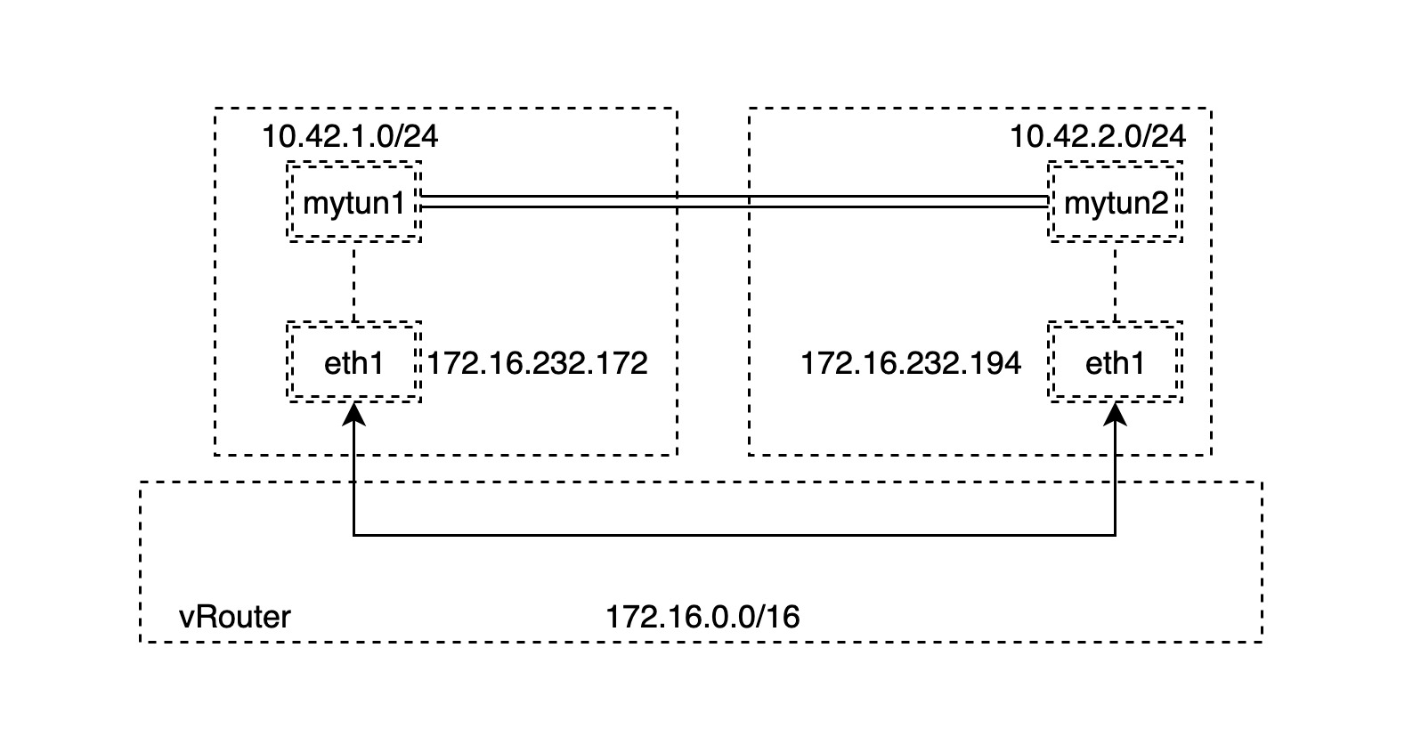
There are two hosts A and B in the same network segment 172.16.0.0/16, so they can be connected directly. What we need to do is to create two different subnets on each of the two hosts.
Note: In fact, the two hosts A and B do not need to be on the same subnet, as long as they are on the same Layer 3 routable network, i.e., they can be routed through the Layer 3 network to build the IPIP tunnel.
To simplify things, we first create the bridge network device mybr0 on node A and set the IP address to the gateway address of the 10.42.1.0/24 subnet, which is 10.42.1.1/24, and then enable the mybr0 bridge device.
Similarly, a similar operation is then performed on node B, but with a subnet address of 10.42.2.0/24.
Next, we create the corresponding TUN network device on nodes A and B respectively.
- create the corresponding TUN network device
- set the corresponding local and remote addresses as the routable addresses of the nodes
- Set the corresponding gateway address to the TUN network device we are going to create
- Enable the TUN network device to create IPIP tunnel
Note: Step 3 is to save and simplify our subnet creation steps by setting the gateway address directly without creating additional network devices.
A:
With the above command, we create a new tunnel device tunl0 and set the remote and local IP addresses of the tunnel, which are the outer addresses of the IPIP packets; for the inner addresses, we set two separate subnet addresses, so that the IPIP packets will be as shown in the figure below.
B:
In order to ensure that we can access the subnets on two different hosts through the IPIP tunnels we created, we need to manually add the following static routes.
A:
|
|
B:
|
|
The routing table for host AB is now shown below.
A:
B:
At this point we can start verifying that the IPIP tunnel is working properly.
A:
|
|
B:
|
|
Yes, it is possible to ping through and we can grab the data at the TUN device with the tcpdump command.
|
|
So far, our experiment is successful. However, it should be noted that if we use gre mode, we may need to modify the firewall settings to allow the two subnets to interoperate, which is more common when building IPv6 tunnels.
one-to-many
In the previous section, we created a one-to-one IPIP tunnel by specifying the local address and remote address of the TUN device. In fact, it is possible to create an IPIP tunnel without specifying the remote address, and the IPIP tunnel will know how to encapsulate new IP packets and deliver them to the destination address specified by the route as long as the corresponding route is added to the TUN device.
To illustrate with an example, suppose we now have 3 nodes that are in the same three-layer network.
Three different subnets are created on each of these three nodes at the same time.
Unlike the previous subsection, instead of directly setting the gateway address of the subnet to the IP address of the TUN device, we create an additional bridge network device to simulate the actual common container network model. We create the bridge network device mybr0 on node A and set the IP address to the gateway address of the 10.42.1.0/24 subnet, and then enable mybr0.
Then perform a similar operation on nodes B and C respectively.
B:
C:
Our ultimate goal is to build IPIP tunnels between each of the three nodes to ensure that the three different subnets can communicate with each other directly, so the next step is to create TUN network devices and set up routing information on nodes A and B respectively.
-
Create the corresponding TUN network device and enable it
-
set the IP address of the TUN network device
-
set the routes to different subnets and specify the next hop address
The corresponding gateway address is the TUN network device that we are about to create.
-
Enable the TUN network device to create the IPIP tunnel
Note: The IP address of the TUN network device is the subnet address of the corresponding node, but the subnet mask is 32 bits, for example, if the subnet address on node A is
10.42.1.0/24, the IP address of the TUN network device on node A is10.42.1.0/32. The reason for this is that sometimes addresses on the same subnet (e.g.,10.42.1.0/24) are assigned the same MAC address and therefore cannot communicate directly through the link layer at layer 2, and if the IP address of the TUN network device and any address are guaranteed not to be on the same subnet, there is no direct communication at the link layer at layer 2. Please refer to Calico’s implementation principle for this point, each container will have the same MAC address, we will have the opportunity to explore it later.
Note: Another point to note is that the
onlinkparameter is specified when setting the route to the TUN network device, to ensure that the next hop is directly to the TUN network device, so that IPIP tunnels can be built even if the nodes are not in the same subnet.
A:
B:
C:
At this point we can start verifying that the IPIP tunnel we built is working properly.
A:
|
|
Everything looks fine. If you ping the other subnets from node B or C respectively, it also works. This shows that we can indeed create one-to-many IPIP tunnels, and the one-to-many IPIP tunneling model is very useful in creating overlay communication models in some typical multi-node networks.
under the hood
We then use the tcpdump command to grab the data from the TUN devices in B and C respectively.
B:
|
|
C:
|
|
In fact, from the process of creating a one-to-many IPIP tunnel, we can roughly guess that Linux’s ipip module gets the internal IP of the IPIP packet based on routing information and then encapsulates it into a new IP packet with an external IP. How is the IPIP packet unpacked? Let’s take a look at how the ipip module receives packets.
|
|
The above code is taken from: https://github.com/torvalds/linux/blob/master/net/ipv4/ip_input.c#L187-L224
As you can see, the ipip module will unblock the packet according to its protocol type, and then unblock the unblocked skb packet again. The above is just some very superficial analysis, if you are interested, we recommend to take a look at the source code implementation of ipip module.