As containers gradually replace virtual machines as the standard for cloud infrastructure today, the network management modules for these containers are dependent on Linux virtual networking devices. In fact, understanding the common Linux virtual network devices is a great benefit to our understanding of container networking and other container-dependent implementations of the underlying network architecture. For now, let’s take a look at what are the common Linux virtual network devices and their typical usage scenarios.
Virtual Network Devices
As we know from the previous note, the drivers for network devices do not interact directly with the protocol stack in the kernel, but rather use the kernel’s network device management module as an intermediate bridge. The advantage of this is that the driver does not need to know the details of the network stack, and the stack does not need to process packets for a specific driver.
For the kernel network device management module, there is no difference between virtual and physical devices, both are network devices and both can be configured with IP addresses. Even logically, both virtual and physical network devices are similar to pipes, where data received from either end will be sent out from the other end. For example, the two ends of the physical network card are the protocol stack and the outside physical network. Packets received from the outside physical network will be forwarded to the protocol stack, and conversely, packets sent by the application through the protocol stack will be sent through the physical network card to the outside physical network. However, different network devices have different driver implementations for where to send packets and how to send them, and it has nothing to do with the kernel device management module and the protocol stack.
In summary, virtual network devices are no different from physical network devices in that they have a kernel stack attached to one end and what the behavior of the other end is depends on the driver implementation of the different network devices.
TUN/TAP
The TUN/TAP virtual network device is connected to the protocol stack on one end, and not to the physical network on the other end, but to another application in user space. This means that packets sent from the stack to the TUN/TAP can be read by the application, and of course the application can send packets directly to the TUN/TAP.
A typical example of using a TUN/TAP network device is shown in the following figure.
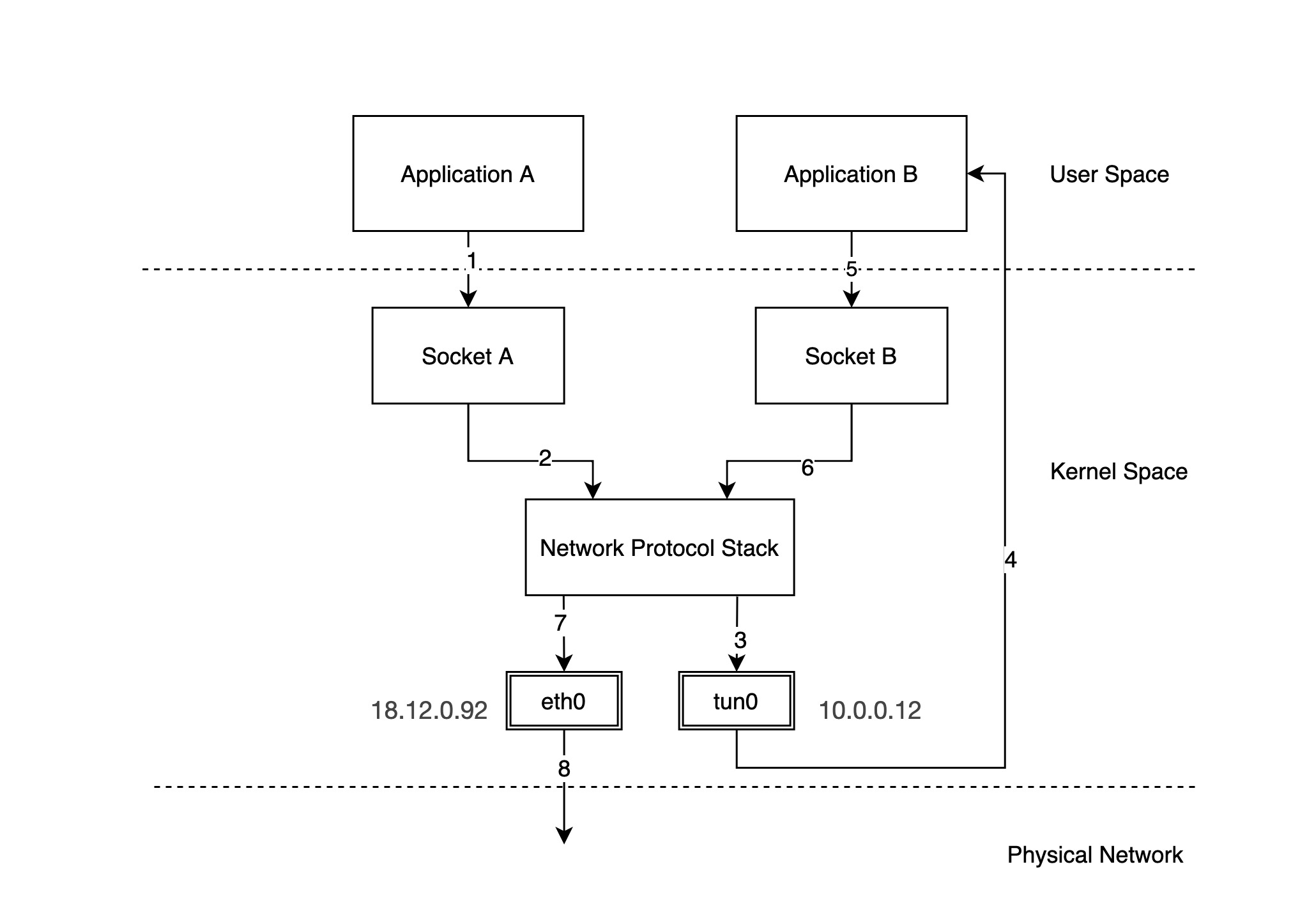
In the above figure, we have configured a physical NIC with IP 18.12.0.92 and tun0 is a TUN/TAP device with IP 10.0.0.12. The packet flow is as follows.
-
Application A sends a packet through socket A. Suppose the destination IP address of the packet is
10.0.0.22. -
Socket A drops the packet to the network protocol stack.
-
The protocol stack sends the packet out to the tun0 device based on the local routing rules and the destination IP of the packet.
-
After receiving the packet, tun0 forwards the packet to application B in user space.
-
Application B receives the packet and constructs a new packet, embedding the original packet in the new packet (IPIP packet) and finally forwards the packet through socket B.
Note: The source address of the new packet becomes the address of tun0, and the destination IP address becomes another address
18.13.0.91. -
Socket B sends the packet to the protocol stack.
-
Based on the local routing rules and the destination IP of the packet, the protocol stack decides that the packet should be sent out through device eth0, and forwards the packet to device eth0.
-
Device eth0 sends the packet out over the physical network.
We see that the network packet sent to 10.0.0.22 is sent to 18.13.0.91 on the remote network using 18.12.0.92 by application B in user space, and the network packet arrives at 18.13.0.91, reads the original packet inside, and forwards it to 10.0.0.22 locally. This is the basic principle of VPN implementation.
Using TUN/TAP devices we have the opportunity to forward some of the packets in the protocol stack to the application in the user space and let the application process the packets. Common usage scenarios include data compression, encryption and other functions.
Note: The difference between a TUN device and a TAP device is that a TUN device is a virtual end-to-end IP layer device, meaning that user space applications can only read and write IP network packets (layer 3) through a TUN device, while a TAP device is a virtual link layer device that can read and write link layer packets (layer 2) through a TAP device. If you use the Linux networking toolkit iproute2 to create a network device TUN/TAP device you need to specify
--dev tunand--dev tapto distinguish between them.
veth
A veth virtual network device is connected to a protocol stack on one end and another veth device on the other end instead of a physical network. A packet sent out of a pair of veth devices goes directly to the other veth device. Each veth device can be configured with an IP address and participate in the routing process of a Layer 3 IP network.
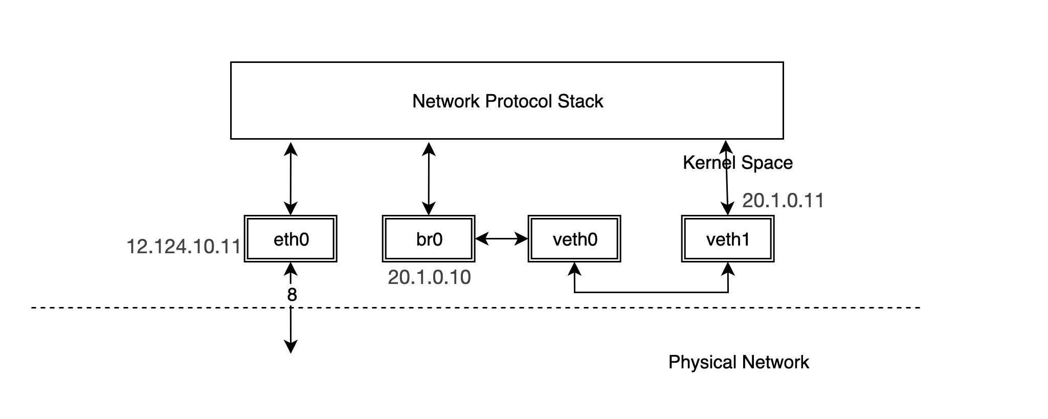
The following is a typical example of using a veth device pair.
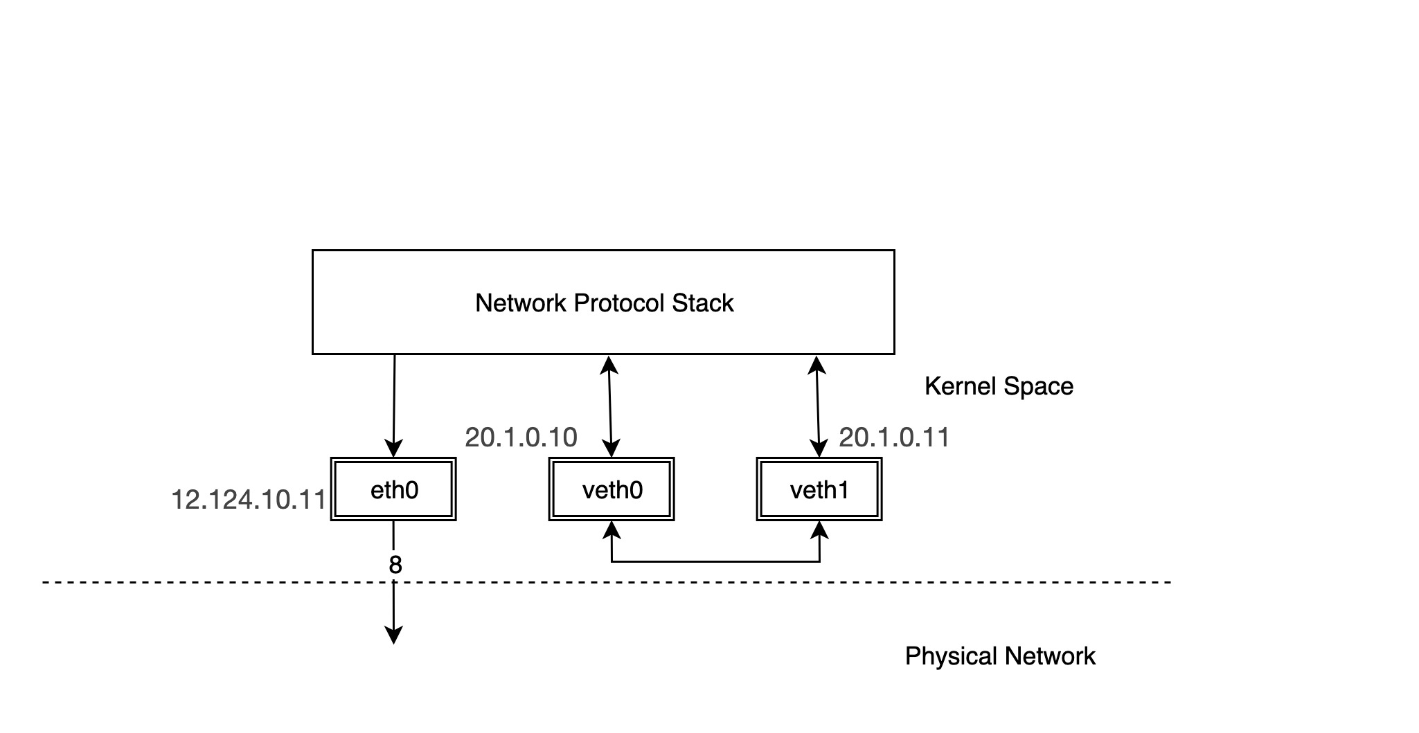
We configure the IP address of the physical NIC eth0 as 12.124.10.11, where the veth device pairs are veth0 and veth1, whose IPs are 20.1.0.10 and 20.1.0.11, respectively.
Then try ping the other device, veth1, from device veth0.
|
|
Note: In some versions of Ubuntu, you may not be able to ping because the default kernel network configuration causes the veth device to fail to return ARP packets, the solution is to configure the veth device to return ARP packets.
You can try using the tcpdump command to see the requested packets on the veth device pair.
|
|
You can see that there are only ICMP echo request packets on veth1, but no answer packets. Think about it. veth1 receives the ICMP echo request packet and forwards it to the protocol stack at the other end, but the protocol stack checks the current device list and finds that there is 20.1.0.10 locally, so it constructs an ICMP echo reply packet and forwards it to the lo device.
The lo device receives the packet and forwards it directly to the protocol stack and then to the ping process in user space.
We can try to use tcpdump to grab the data on the lo device.
|
|
It can be seen that for pairs of veth devices, packets going out from one device will be sent directly to the other device. In practical application scenarios, such as container networks, pairs of veth devices are in different network namespaces, and packets are forwarded between different network namespaces, as will be explained later in the introduction of container networks.
bridge
A bridge is a virtual network device, so it has the characteristics of a virtual network device and can be configured with IP and MAC addresses. Unlike other network devices, the bridge is a virtual switch with similar functions to a physical switch. bridge has a protocol stack attached to one end and multiple ports on the other end, and data is forwarded between the ports based on MAC addresses.
The bridge can work at either layer 2 (link layer) or layer 3 (IP network layer). By default, it works at layer 2 and can forward Ethernet messages between different hosts on the same subnet; when an IP address is assigned to the bridge, it enables the bridge to work at layer 3. Under Linux, you can manage the bridge with the command iproute2 or brctl.
Creating a bridge is similar to creating other virtual network devices, except that you need to specify the type parameter as bridge.
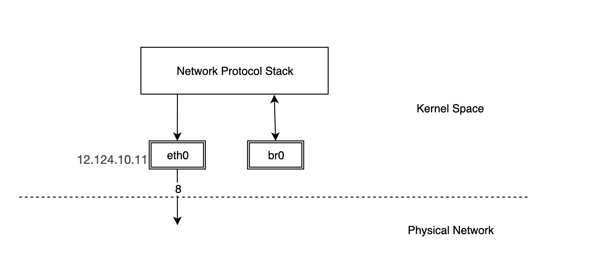
But this creates a bridge with a protocol stack connected to one end and nothing connected to the other ports, so we need to connect other devices to the bridge to have any real functionality.
|
|
In fact, once br0 and veth0 are connected, they become bidirectional channels, but the kernel protocol stack and veth0 become unidirectional channels. The protocol stack can send data to veth0, but the data veth0 receives from the outside is not forwarded to the protocol stack. Also the MAC address of br0 becomes the MAC address of veth0. We can verify this.
If we use tcpdump to capture packets on br0 we will see that:
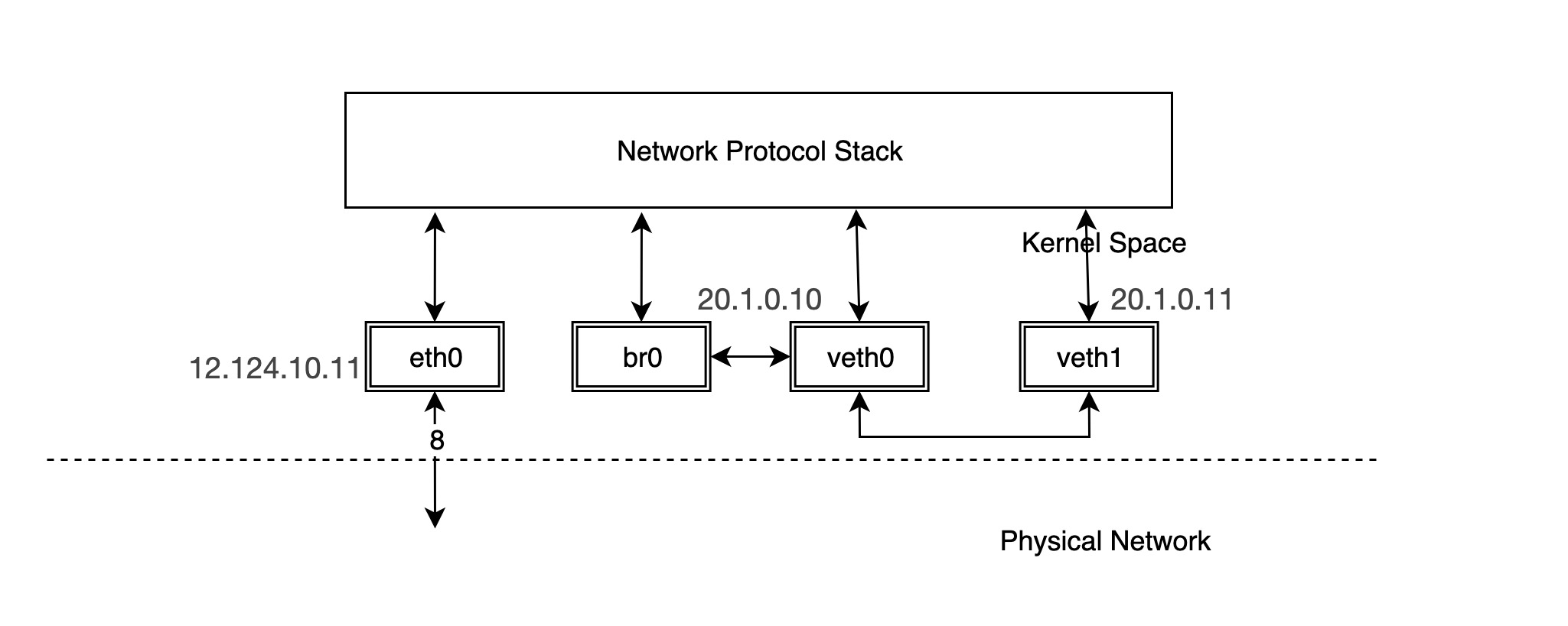
You can see that veth0 receives the reply packet and forwards it directly to br0 instead of giving it to the protocol stack, so the protocol stack does not get the MAC address of veth1 and thus the ping fails. br0 intercepts the packet between veth0 and the protocol stack. But what happens if we configure the IP for br0?
Thus, the network structure becomes the following.
At this point, you can ping veth1 via br0 and find that it works.
|
|
In fact, when the IP of veth0 is removed and the IP is configured for br0, the protocol stack will not send packets to veth0 when routing. To express it more intuitively, the connection line between our protocol stack and veth0 is removed and veth0 is equivalent to a network cable at this time.
In reality, bridge is commonly used in the following scenarios.
Virtual Machine
A typical virtual machine network implementation is to connect the NIC in the virtual machine to the br0 of the host through TUN/TAP, when br0 is similar to the physical switch, the packets sent out by the virtual machine first reach br0, and then br0 is handed over to eth0 to send out, so that the packets do not need to go through the host’s stack, which is very efficient.
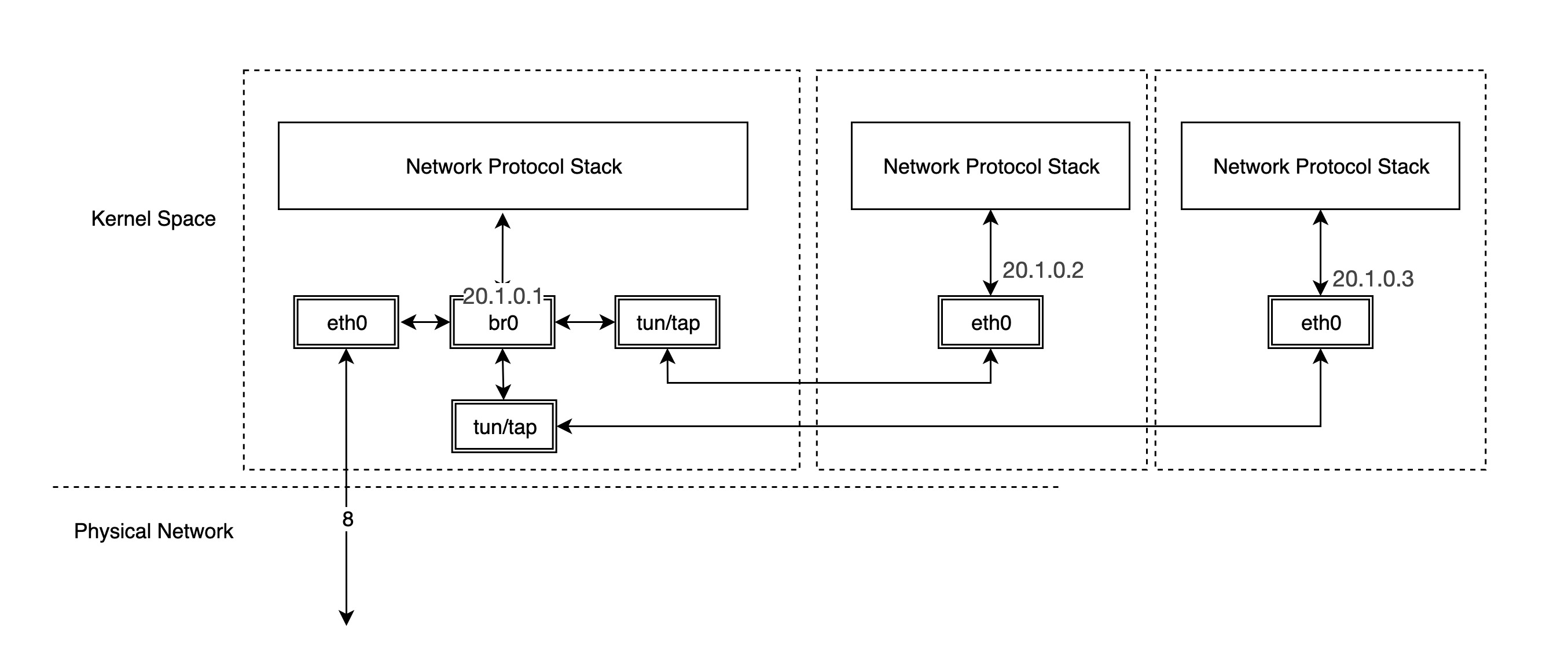
Container
As for container networks, each container’s network device is in a separate network namespace, so it is good to different container’s protocol stack, we further discuss the different container network implementations in the next notes.
Ref
https://backreference.org/2010/03/26/tuntap-interface-tutorial/https://blog.scottlowe.org/2013/09/04/introducing-linux-network-namespaces/https://www.ibm.com/developerworks/cn/linux/1310_xiawc_networkdevice/http://ifeanyi.co/posts/linux-namespaces-part-1/http://www.opencloudblog.com/?p=66