When I used to look at k8s related knowledge, my network knowledge was relatively weak, so I didn’t understand the Flannel network. So recently I researched some knowledge of cloud-native virtual networks and wrote two articles: VXLAN Protocol for Cloud-Native Virtual Networks and Cloud-native virtual networking tun/tap & veth-pair which introduced some knowledge of virtual networks. These are all for flannel, and now we finally come to the Flannel article.
Overview
Before we discuss Flannel, let’s take a look at Docker’s networking model. By default, Docker uses the bridge network mode.
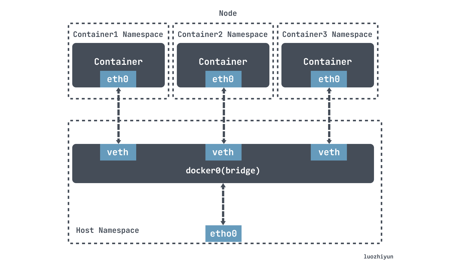
Docker will create a docke0 virtual bridge during installation, then when running the container, create a virtual NIC veth pair device on the host. veth pair devices come in pairs, thus forming a data channel, data coming in from one device will come out from the other. Put one end of the veth pair device in the newly created container named eth0, and the other end in the host docker0, named with the prefix veth, which I described in the previous article Cloud-native virtual networking tun/tap & veth-pair.
Under the default configuration of Docker, the docker0 bridges on one host are not associated with the docker0 bridges on other hosts, and there is no way for them to connect to each other. Therefore, the containers connected to these bridges have no way to communicate with each other.
This is where Flannel comes in, which is the main container networking solution from CoreOS. The implementation principle is equivalent to adding an overlay network on top of the original network, where the nodes can be seen as connected by virtual or logical links.
Flannel runs a flanneld agent on each host, which is responsible for pre-assigning a Subnet subnet to the host and assigning an ip address to the Pod. Flannel uses Kubernetes or etcd to store network configuration, assigned subnet and host public ip information, and packets are forwarded via VXLAN, UDP or host-gw types of backend mechanisms.
Installation
I used kubeasz for the installation, and generally refer to this document: https://github.com/easzlab/kubeasz/blob/master/docs/setup/00-planning_and_overall_intro.md, based on which we can quickly We can build a complete k8s cluster quickly.
After using the command docker exec -it kubeasz ezctl new cluster name, the corresponding cluster configuration will be generated in the /etc/kubeasz/clusters/ directory.
As we want to customize the network plugins, remember to modify the /etc/kubeasz/clusters/clusters/hosts file to configure the node information and network plugins.
|
|
Then modify the Flannel backend configuration /etc/kubeasz/clusters/cluster name/config.yml.
You can destroy the environment after each use and then reinstall it. Each reinstallation and destruction is automatic, and believe me, it’s the fastest.
|
|
Note that the udp mode is too old and now deprecated, so it is not possible to install it this way. I haven’t found a better way to install it yet.
Subnet
Flannel To create an overlay network for a cluster, the first step is to plan the ip address of each host container. For example, if I have a three-node k8s cluster, we can see the subnets by running the following command.
By examining the other two nodes, we can see that in the Flannel network, each pod is assigned a unique ip address and each k8s node has a non-overlapping subnet with no intersection.

Let’s take a look at how subnets are assigned.
When Flannel is installed, the network segments for the entire cluster are typically set up, as well as the length of the subnets.
|
|
When you first start Flannel, you run flanneld as an agent in the host, then select an unused subnet from the corresponding network segmentation range as the local subnet, e.g. 172.20.0.1/24, and report it to etcd, using the k8s api or etcd for storing the network configuration of the entire cluster. The network segment used by the cluster is recorded according to the configuration.
etcd ensures that the configuration seen by flanned on all nodes is the same. At the same time, the flanned on each node listens to the data changes on etcd and senses the changes of the nodes in the cluster in real time, so that the IPs of the whole cluster are not conflicting with each other.
Flannel backend
About Flannel backend The following is about udp, vxlan, host-gw.
udp
udp is the earliest mode supported by Flannel. There are two main components in this mode: flanneld and flannel0. The flanneld process is responsible for listening to network changes on etcd and sending and receiving packets, while flannel0 is a Layer 3 tun device that is used to pass ip packets between the OS kernel and user applications.
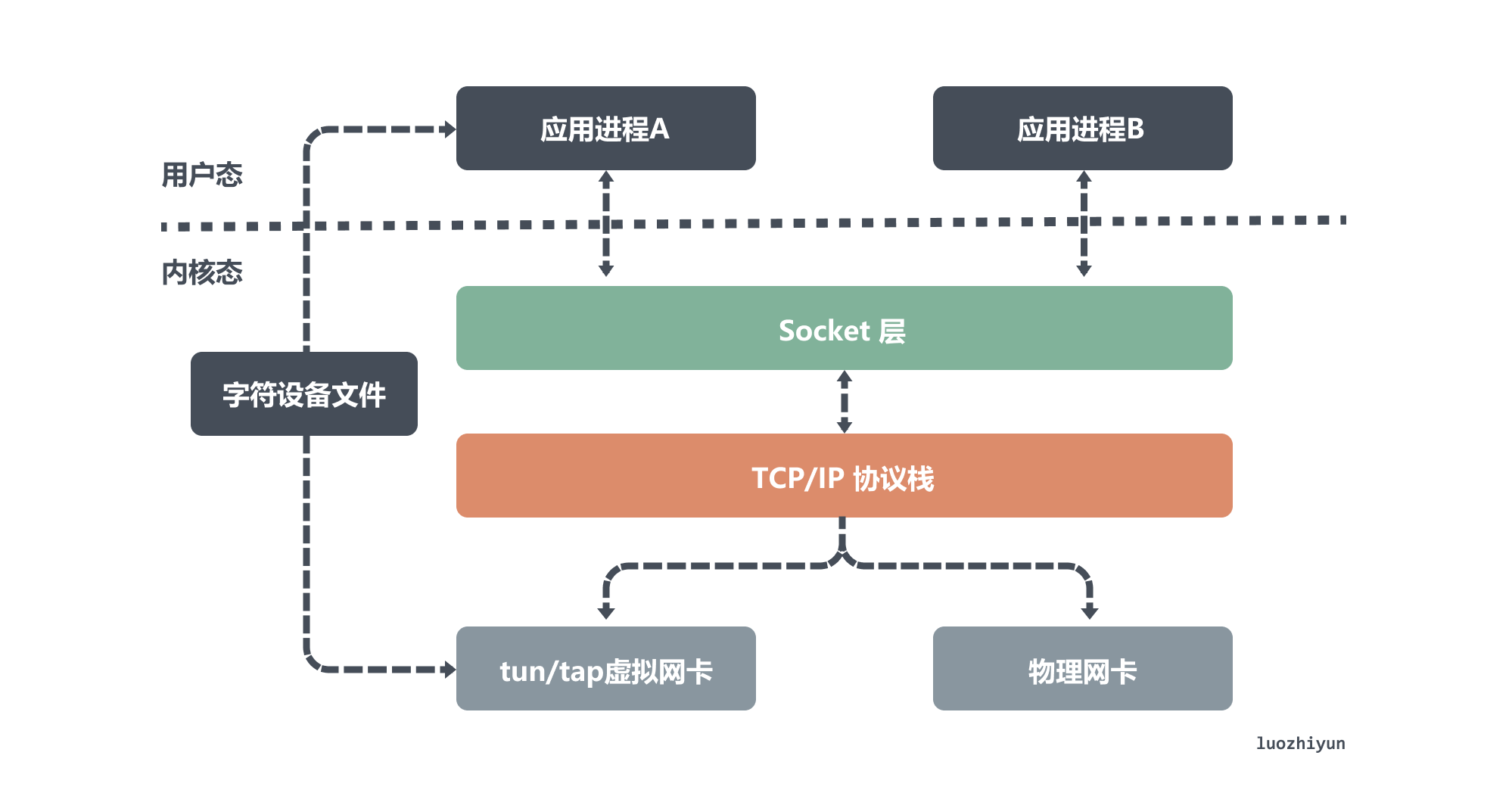
As shown above, the tun device is a Layer 3 network layer device, which is used to emulate a virtual NIC and can access each other directly through its virtual IP. tun device reads and writes packets from the /dev/net/tun character device file, and application process A listens to the packets coming from a port and is responsible for sealing and unpacking the data.
All packets sent from application process B to another virtual ip will be packetized by application process A and then sent out; data sent to that virtual NIC will first be sent to the port that application process A is listening to, and then unpacketized by it and sent to application process A. So it is the same for flannel0.
The following diagram shows the data processing process in udp mode.
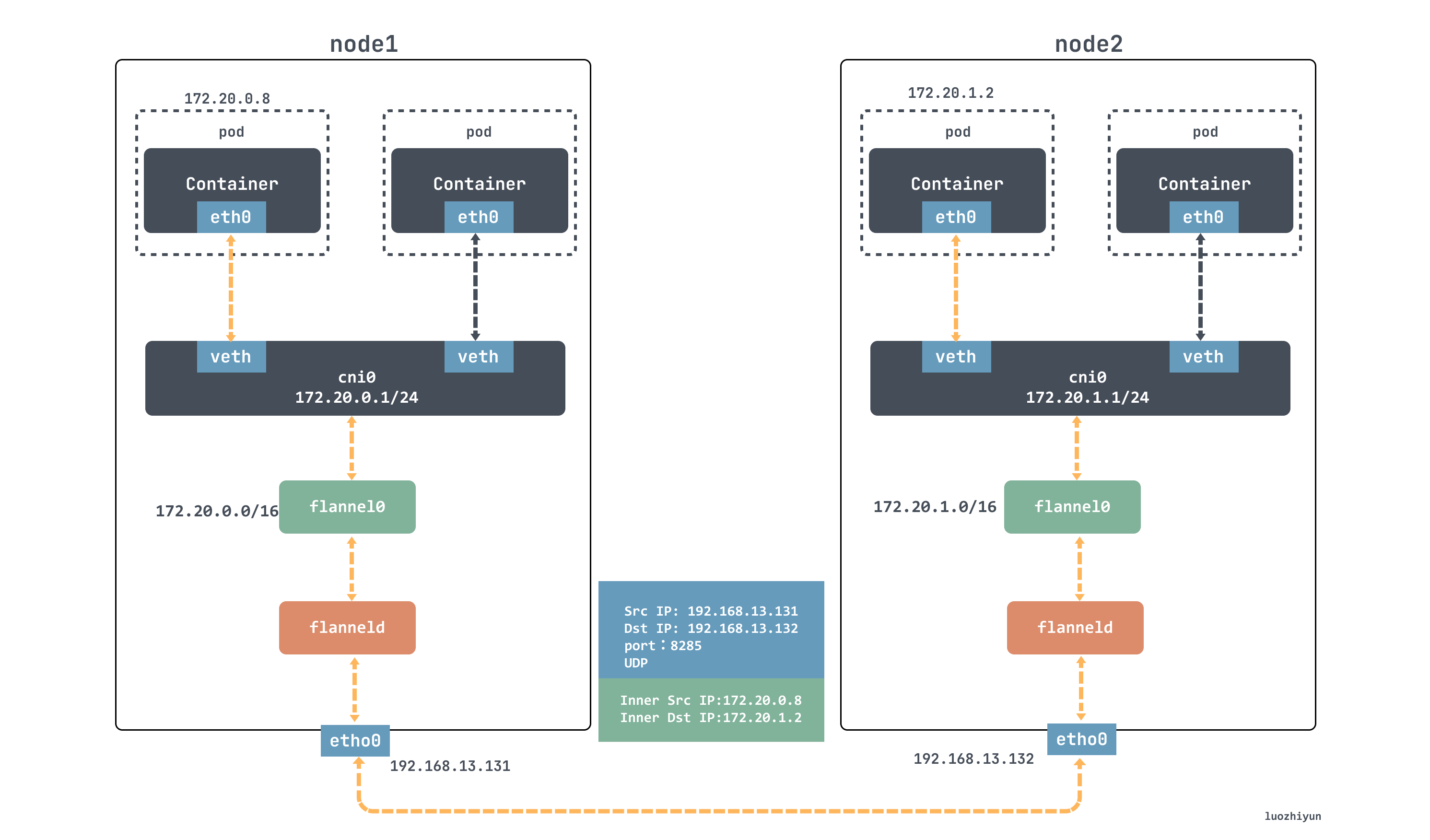
As shown in the diagram, the container with ip 172.20.0.8 wants to send data to the 172.20.1.8 container of another node, this packet will be given to the flannel0 device first according to the ip route, then flannel0 will take this ip packet and give it to the application that created this device, which is the flanneld process. process is a udp process that handles the packets sent by flannel0.
The flanneld process will listen to the etcd network information, then match the destination ip address to the corresponding subnet, find the IP address of the host node corresponding to this subnet from etcd, then encapsulate this packet directly in the udp packet and send it to node 2.
Since flanneld on each host listens to port 8285, the flanneld process on the node 2 machine will get the incoming data from port 8285, parse it out and send it to the source ip address encapsulated in it.
flanneld sends this ip packet directly to the tun device it manages, which is the flannel0 device. The network stack then sends the packet based on the route to the cni0 bridge, which acts as a layer 2 switch and sends the packet to the correct port, which then enters the container through the veth pair device.
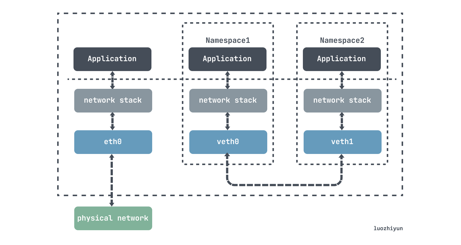
As for the veth-pair, it is a pair of virtual device interfaces that come in pairs, with one end connected to the protocol stack and one end connected to each other, so that data entered at one end of the veth device will flow out of the other end of the device unchanged. The veth in k8s is directly connected to the cni0 bridge, which can be used to send data to different containers on the same node.
The Flannel udp mode described above is now deprecated because it goes through three copies of data between the user and kernel states. The container sends the packet once through the cni0 bridge into the kernel state; the packet goes from the flannel0 device to the flanneld process once more; and the third time, flanneld reenters the kernel state after udp blocking and sends the UDP packet through the eth0 of the host.
VXLAN
Before talking about VXLAN mode, let’s see what VXLAN (Virtual Extensible Local Area Network) is, it is a network virtualization technology supported by Linux kernel itself.
VXLAN uses the L2 over L4 (MAC in UDP) message encapsulation mode, which puts the Ethernet frames originally transmitted at Layer 2 into the message body of Layer 4 UDP protocol, and adds its own VXLAN Header, which has 24 Bits of VLAN IDs directly in the VXLAN Header, and can store 16.77 million different values. VXLAN works on Layer 2 networks (the ip network layer) and can be deployed on any network that is Layer 3 reachable (able to communicate with each other via ip). the entire message structure of VXLAN is shown below.
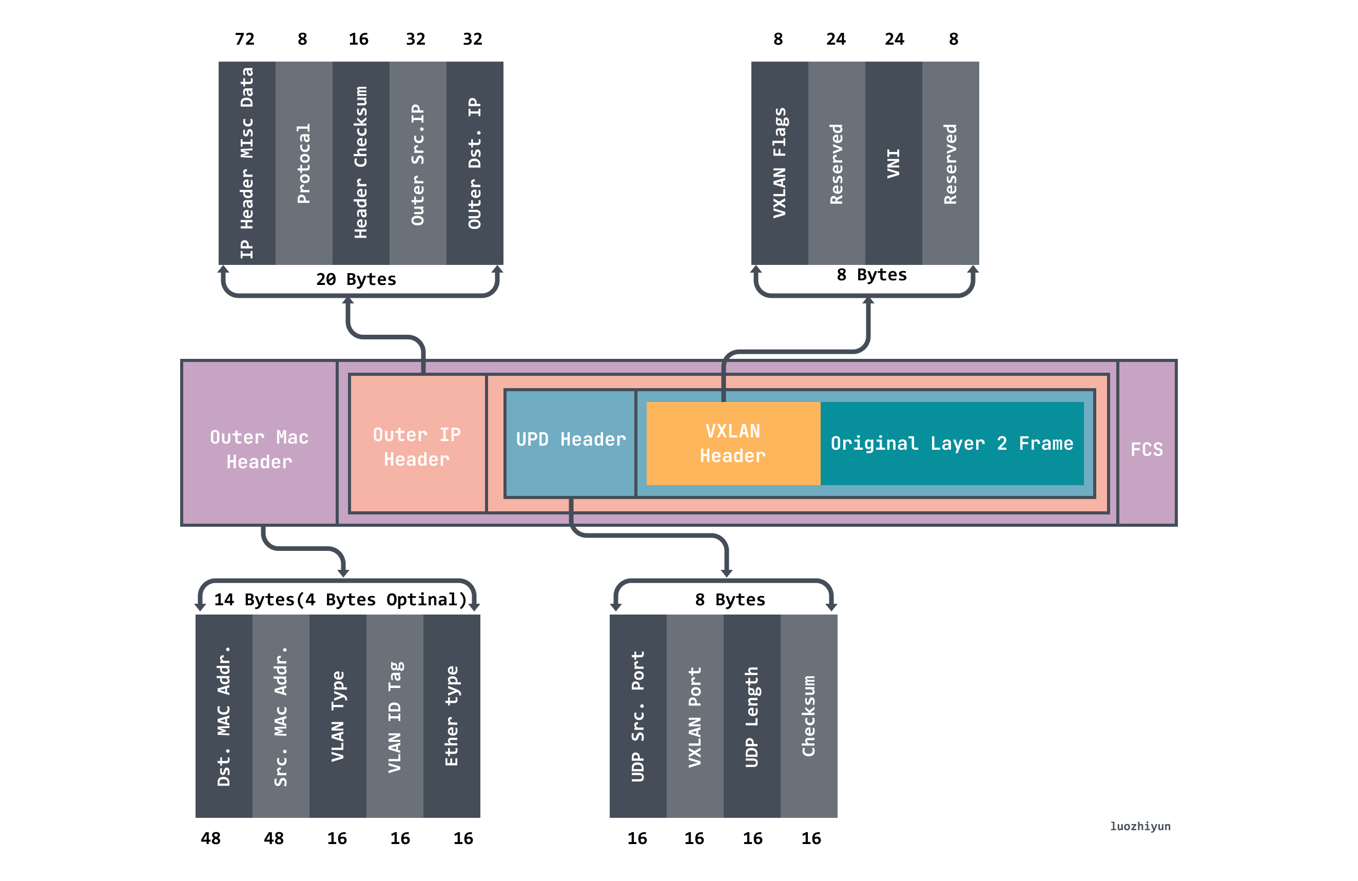
Through the above message, we can know that it is actually the inner layer of data messages wrapped in another layer, and then through a process called VTEP is responsible for unpacking and sealing packets.
There is also a VNI flag in the VXLAN header, which is mainly used to mark whether the packet belongs to the current tenant and is used for network isolation.
When VXLAN is communicating, VTEP will determine the destination VTEP address by querying the forwarding table FDB before communication. The forwarding table FDB is used to store the MAC address of the remote VM/container, the remote VTEP IP, and the VNI mapping relationship, which is automatically updated by Flannel on k8s through the flanneld process.
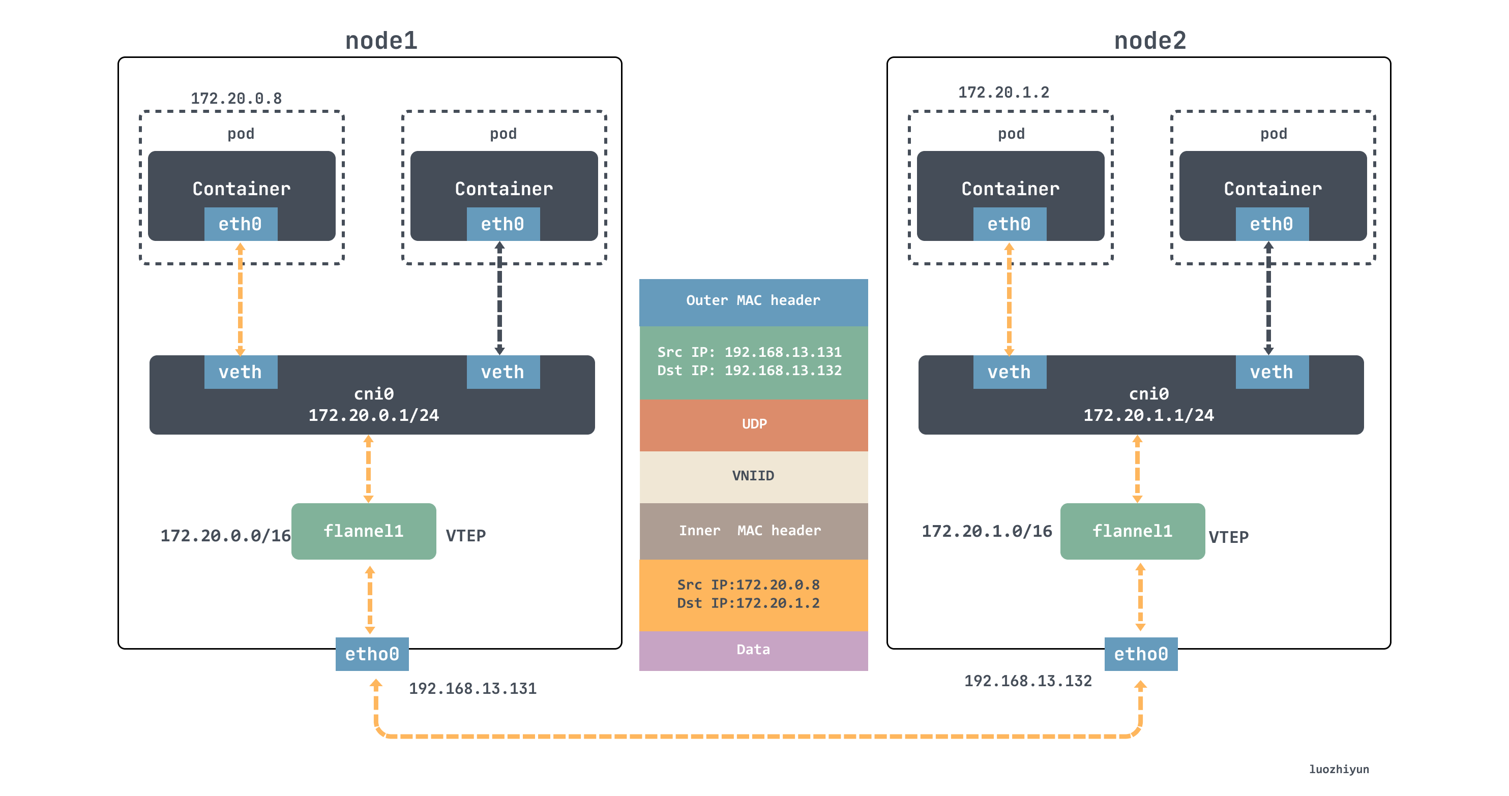
For example, if the container in node1 wants to communicate with the container in node2, it will go through the following.
- Sender:
ping 172.20.1.2is initiated in node1, theICMPmessage passes through thecni0bridge and is handed over to theflannel.1device for processing. Theflannel.1device is a VTEP device for VXLAN and is responsible for VXLAN packet unpacketization. Therefore, on the sending side,flannel.1encapsulates the original L2 packets into VXLAN UDP packets and sends them frometh0. - Receiver side: node2 receives the UDP message, finds out it is a VXLAN type message, and hands it to
flannel.1for unpacking. Based on the destination ip in the original packet, the original packet is sent to the corresponding container via thecni0bridge.
host-gw
The host-gw mode communication is very simple, it is through the ip route direct connection way to communicate, flanneld is responsible for setting the route for each node, the next hop address of the corresponding node Pod subnet will point to the corresponding node’s ip.
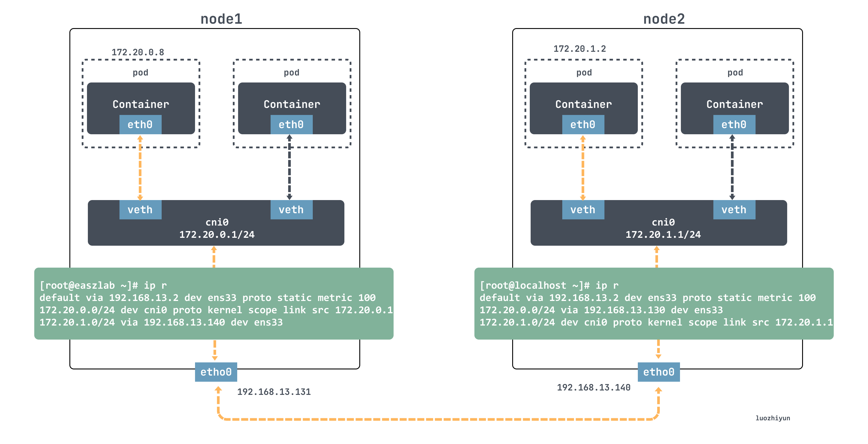
For example, if the node1 container wants to access the node2 container, it will match the following routing rule on the node1 node.
This routing rule will send the ip packet whose destination ip address belongs to the 172.20.1.0/24 segment through the local ens33 device (i.e., dev ens33); and, its next-hop address (next-hop) is 192.168.13.140.
Once the next-hop address is configured, then when the ip packet is encapsulated into a frame from the network layer into the link layer, the ens33 device will use the MAC address corresponding to the next-hop address as the destination MAC address of the frame. Obviously, this MAC address is the MAC address of node2.
After node2 gets the ip packet from the frame, it finds that the destination ip address of the ip packet is 172.20.1.2, and then it matches the routing rule above node2.
Then it goes to the cni0 bridge and then to the corresponding container.
From the above, we can see that the core of the host-gw mode working properly is that the ip packet, when encapsulated into a frame and sent out, will use the next hop in the routing table to set the destination MAC address. This way, it goes through the Layer 2 network to the destination host. Therefore, Flannel host-gw mode must require Layer 2 connectivity between the cluster hosts.
Summary
This article first used kubeasz to quickly build our experimental environment, so that you can quickly simulate one on your own machine. Then we talked about some of the communication mechanisms of Flannel, including subnetting, the three backends (udp, vxlan, host-gw), etc., and studied their implementation principles.
Comparing the three networks, udp mainly uses tun devices to simulate a virtual network for communication; vxlan mode mainly uses vxlan to implement a three-layer overlay network, using flannel1, a vtep device, to seal and unseal packets, and then route and forward them to achieve communication; and host-gw network is more direct, directly changing the routing information of the Layer 2 network to achieve packet forwarding. The host-gw network is more direct, directly changing the routing information of the Layer 2 network to achieve packet forwarding, thus eliminating the intermediate layer and achieving higher communication efficiency.